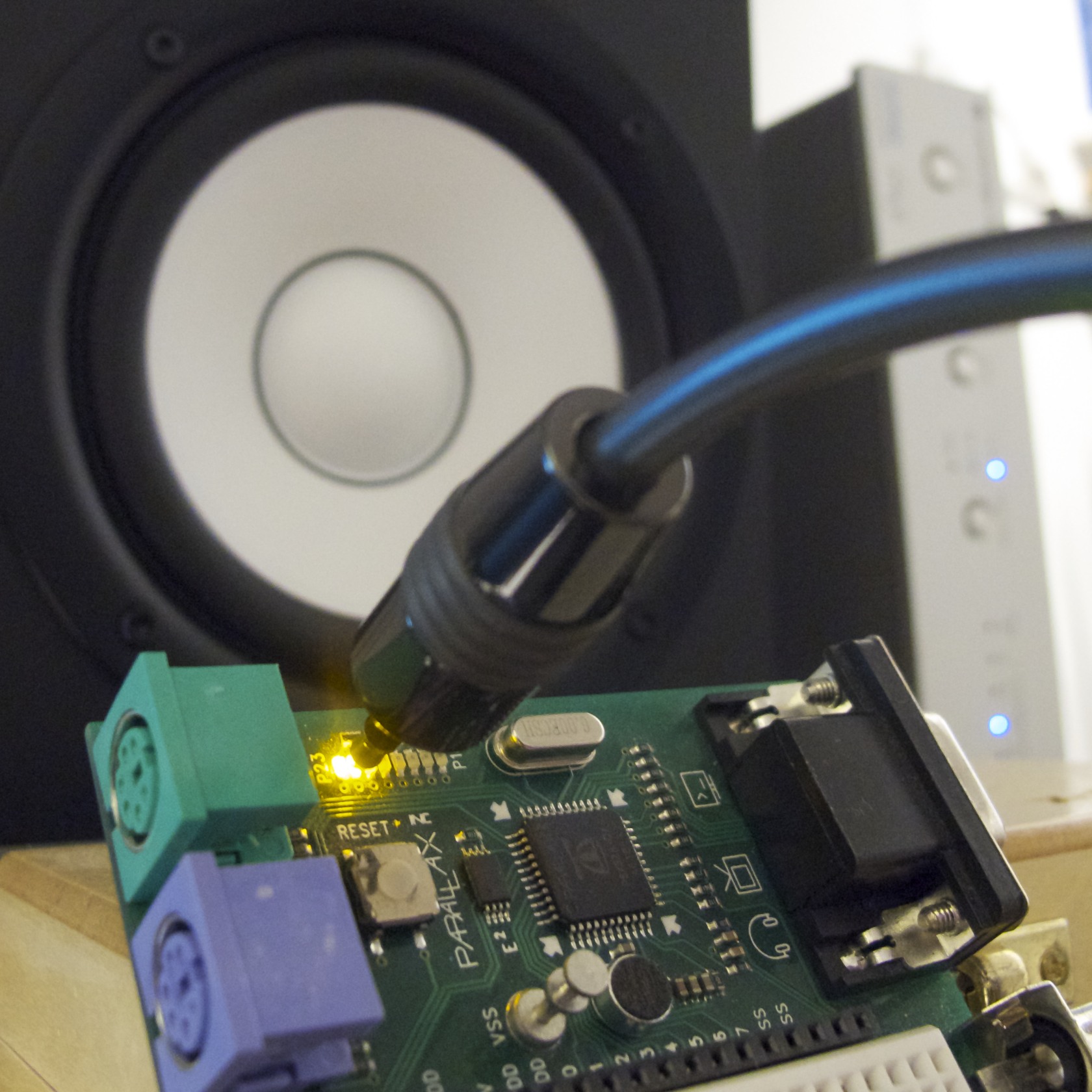
A few years ago, I implemented an S/PDIF encoder object for the Parallax Propeller. When I first wrote this object, I wrote only a very terse blog post on the subject. I rather like the simplicity and effectiveness of this project, so I thought I’d write a more detailed explanation for anyone who’s curious about the gritty details.
This is a recent video by Nick at Gadget Gangster where he takes the S/PDIF object for a test drive. [via Oldbitcollector]
The source code is open, under an MIT-style license. If you’re a fellow Propeller fan, it’s pretty easy to use this code to give your next sound project a digital output. If not, read on… perhaps you will be inspired to try exploring digital audio on a different microcontroller platform!
Digital Audio Primer
Starting from the very basics… what is S/PDIF, and why would we even want to generate it directly from a microcontroller?
Microcontroller audio projects are getting more and more popular, especially as legions of Arduino hackers build DIY drum machines, noise makers, 8-bit synthesizers, and so on. Many of these bit-bang low-fi audio in software. Some of them use external analog synthesizers, MP3 decoders, or other support ICs. If you wanted high-fidelity audio, though, your options get more limited. Some microcontrollers (like the Propeller) can perform PWM at a high enough frequency to produce reasonable audio quality. But this is still no match for an external DAC, much less a high-quality external DAC. So, if you’re really trying to produce higher quality audio without a lot of extra fuss or expense, it makes some sense to let someone else do the job.
If you have a hi-fi stereo receiver, you already have an external DAC and a good way to communicate with it. Nearly all consumer audio receivers now include digital audio inputs based on the Sony/Phillips Digital Interconnect Format (S/PDIF) standard. This consumer standard is actually a variant of the professional AES3 standard. Electrically, this is a high speed unidirectional serial link with a clock that runs at a high multiple of the audio sample rate. The physical transport can be a low-voltage signal over 75-ohm coax, or it could be optical. Optical interconnects (with TOSLINK connectors) are especially common, and to transmit these signals all you need is an LED.
For every audio sample. this digital signal transmits all of the bits in the sample, as well as some control information. Also, quite importantly in fact, it transmits the timing of these samples. The DAC synchronizes its conversion cycles to the time-of-arrival of each sample that comes over the digital bitstream. So, the analog timing characteristics inherent in this digital signal can also influence the resulting analog signal.
Sound nerds tend to get fabulously stressed out over jitter and wander and so on— names for different kinds of deviations from optimal bit timings. It’s good to keep in mind that, by nature, S/PDIF is a much more real-timey sort of signal than your average serial data link. But unless you’re the sort of hopeless audiophile who spends more on your amplifier power cables than I’d spend on a car, you probably shouldn’t get too bent out of shape over a few nanoseconds here or there.
S/PDIF Data Format
S/PDIF uses a serial signal clocked at 64x the audio sample rate. So, for 48 kHz audio, we need a serial signal at a whopping 3.072 megabits per second! However, the receiver doesn’t just need the bits, it also needs a clock. Since we only have one electrical or optical signal to work with, both the clock and data have to be recoverable from this one signal. S/PDIF does this using Biphase Mark encoding, which is a close relative of Manchester code. Because of this coding, we actually have to transmit on a clock rate which is 2x the bit rate. So, again for 48 kHz audio, we need a transmit clock of 6.144 MHz.
But wait, why 64x the sample rate? Even if we’re transmitting stereo audio at 24 bits per sample, that’s only 48 bits. Where do the other bits go?
Some of them are used by S/PDIF for synchronization purposes, and some are used for a low-frequency signaling channel which can transmit status words at a rate much slower than the audio sample rate, and some are effectively useless to us, reserved for obsolete or infrequently-used standards. The most primitive grouping of bits understood by S/PDIF is a 32-bit subframe which encodes one sample for one audio channel:

So many bits… what does it all mean???
- The preamble identifies the type of subframe, as we’ll see below. It is the only part of the stream which is not biphase-mark encoded. It is the only place where we’ll see a run of three clock cycles with no bit transitions, so this allows the receiver to uniquely identify the preamble within the received bitstream.
- Each subframe includes 24 bits of audio data, transmitted LSB-first and biphase-mark encoded. The low 4 bits of this stream may be used for other purposes, depending on which standard you’re reading.
- The Valid bit indicates that this subframe contains valid sample data, and it is okay to output. In practice this bit isn’t really useful, since with the advent of Dolby compressed audio over S/PDIF, the receiver has a lot more work to do in order to determine if the data is valid uncompressed audio.
- The User and Control bits are both part of a lower-bandwidth serial stream that we’ll see later.
- And finally, each subframe has a Parity bit to help detect single-bit errors.
The User and Control bits on each channel collectively form four low-bandwidth serial channels, each running at a rate of one bit per sample. In S/PDIF, the User bit is unused, and the Control bits on each channel transmit a 192-bit Channel Status word. This word is fully transmitted once per block where a block is defined as a group of 192 frames beginning with a Z preamble.

In the professional AES3 protocol, there is a lot of data packed into this status word. But S/PDIF uses it for very little. In fact, only 13 of these bits are used at all, and in practice there isn’t really anything useful in this word. AES3 encodes an exact sample rate here, but in S/PDIF the only indication of sample rate is the clock recovered from the S/PDIF bitstream itself.
Biphase Mark Code
Wow, so far this looks pretty easy. Well, except for the high bit rate, and the picky timing. But what about this biphase mark code?
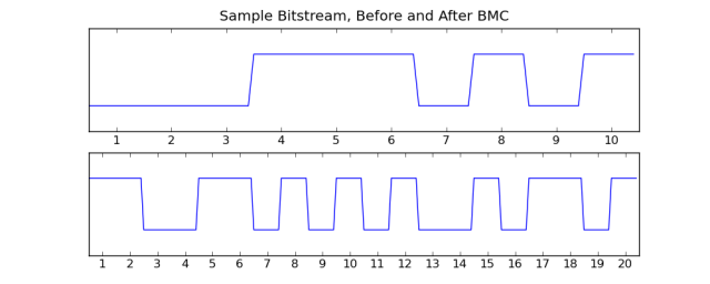
There are a few different ways to think of biphase mark encoding. If you’re familiar with Frequency Shift Keying (FSK) modulation, it might make sense to think of BMC as a particular form of FSK. A string of ones would be encoded as a square wave at a frequency equal to the original bit rate. A string of zeros would be a square wave at half that frequency. Put another way, you can think of BMC in terms of bit transitions. A zero bit is encoded by a transition followed by a non-transition, whereas a one bit turns into two transitions.
This demystifies BMC a bit… but why do it at all? Well, like any protocol which has to travel over some kind of analog physical media, very low-frequency signals (down to and including DC) can be troublesome. Let’s say we’re using an optical TOSLINK cable to transmit S/PDIF, and we have two theoretical bitstreams. One of them always transmits “one” bits, the other always transmits “zero” bits. The first bitstream means the transmitter’s LED is always on, and the second means the LED is always off. How does the receiver tell these two streams apart?
At first it seems obvious. The “one” stream is brighter than the “zero” stream. But actually, this might not be true. Maybe the first stream has a very dim light or a long cable. Maybe the second stream has a light leak around the receiver. It’s unreliable to rely on any absolute amount of light to discriminate ones from zeros, and in fact it’s not that hard to imagine situations where one system’s zero is brighter than another system’s one.
Similar problems exist in many kinds of analog transmission problems. Radio receivers, for example, need to deal with a very wide range of signal strengths. Unbalanced coaxial cables, such as S/PDIF over copper, can face similar problems. The receiver circuit in each of these cases needs to employ some kind of automatic gain control (AGC). AGC circuits track the average power level of the received signal, and “center” the one/zero discrimination threshold around this value. It’s a simplification, but AGC circuits can also be thought of as high-pass filters, since they subtract the unknown DC bias in the received signal.
Since DC signals are removed by the receiver, we can’t use them to carry any useful data. Those hypothetical all-zero or all-one bitstreams would be a disaster, since the receiver would continuously detect a signal level equal to the average. Any tiny amount of electrical noise would be detected as a one or zero.
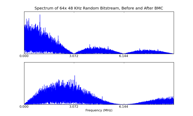
This is where BMC helps. We can use a simple SciPy simulation to plot unencoded and encoded bitstreams in the frequency domain:
Now it’s easy to see that BMC is in fact shifting the signal up in the frequency domain. It needs twice the bandwidth now, but the center frequency is now near the bit rate, and we no longer have any signal at DC. Hooray, no more grumpy receiver AGC.
Microcontroller Implementation
Typically if you were generating an S/PDIF signal, it would be sane to use an FPGA or an ASIC. In silicon. But this article is about breaking the mold and doing it in pure software. Why? For fun, and maybe also to lower the barrier to entry on digital audio. There are a few challenges to overcome, though:
- Need to have enough CPU left over to generate the audio signal in the first place
- Very high bit rate for a software implementation
- Strict bit timing, at an unusual frequency
- Biphase mark encoding is not parallelizable
My platform of choice for this project was the multi-core Parallax Propeller, since it’s simple and hobbyist-friendly yet it also has features which directly address these challenges. The XMOS XCore, another parallel microcontroller, would also be a fabulous choice. It may also be possible to implement S/PDIF on a sufficiently fast single-core microcontroller. Unfortunately, an 8-bit µC like the AVR used in the popular Arduino board probably wouldn’t be fast enough.
Edit: Actually, perhaps it would be doable on the Arduino after all… you would just need a less common crystal frequency. To generate an S/PDIF signal with a 32 KHz sample rate, for example, you could run the AVR at 16.384 MHz. The encoded bitstream clock would need to be 4.096 MHz (32k * 64 * 2), and you can program the AVR’s SPI master to transmit at up to half the main oscillator frequency. So you could run the AVR at 8.192 MHz or 16.384 MHz. At the latter frequency, you would have 32 instructions for every 8 bits of encoded bitstream data. That should be enough to do the encoding in an ISR and have a little time left over for applications…
A multi-core microcontroller makes challenge (1) a piece of cake. On the Propeller, one of the eight CPU cores can be dedicated to S/PDIF encoding. The other seven are available for application code, sound streaming or synthesis, and for other I/O devices.
Challenges (2) and (3) can be mitigated if we have a little bit of help from hardware. If we were using traditional bit-banging, and toggling I/O pins in code, a very fast processor would be needed. Even if the encoding and output could be done in four instructions per bit, just the S/PDIF encoding would require a little over 24 MIPS of processing power. Annoyingly, the CPU clock would have to be run at a multiple of the audio bit rate. You would have no way to use a separate clock. But if we had some hardware to shift out bits at the right time, the CPU can spend that time doing other tasks. Many microcontrollers have an SPI port that may be able to do the job. The XCore actually has special-purpose shift register hardware just to help with high-speed I/O tasks like this. And the Propeller has something close enough— a “video generator” that can be configured as a latch and shift register. The Propeller’s video generator can be clocked by a PLL that we program to synthesize the audio bitstream clock.
Challenge (4) means we need at least a small amount of code which runs serially for every bit in the audio bitstream. The problem is similar to calculating parity. Every input bit affects all subsequent output bits. In my implementation, I just use the fastest unrolled loop I can to perform the biphase mark encoding in two instructions per bit. Here’s an excerpt from the meatiest part of the BMC implementation:
              ' Load the preamble. The preamble is not biphase encoded,
              ' but it is subject to being inverted if the previous cell
              ' was a 1. This step is omitted for the second half (second
              ' 32 cells) of a subframe.
              '
              ' In biphase encoding, every bit unconditionally begins with
              ' one transition. We can add these transitions too, in the same
              ' operation.
              '
              ' The masks below select all cells in the biphase register that are
              ' output after the bit we're currently encoding. Any time we
              ' XOR the biphase register with the mask, we're creating a
              ' transition on all future bits. The mask starts at the first
              ' odd numbered non-preamble bit.

              xor     biphase, preamble

              ' To actually biphase encode our input data, we'll insert
              ' additional transitions every time there's a 1 bit in our input.
              ' For the first half of the subframe, we're processing 12 bits
              ' of subframe data. (16, minus the 4-bit preamble)
              '
              ' The loop is unrolled, since this is very speed-critical. At
              ' 48 KHz, we have less than three instructions per bit!

              rcr     subframe, #1 wc     ' Extract the next LSB from the subframe
    if_nc     xor     biphase, mask_4     ' Insert a transition only for '1' bits.
              rcr     subframe, #1 wc
    if_nc     xor     biphase, mask_5
              rcr     subframe, #1 wc
    if_nc     xor     biphase, mask_6
              rcr     subframe, #1 wc
    if_nc     xor     biphase, mask_7
              rcr     subframe, #1 wc
    if_nc     xor     biphase, mask_8
              rcr     subframe, #1 wc
    if_nc     xor     biphase, mask_9
              rcr     subframe, #1 wc
    if_nc     xor     biphase, mask_10
              rcr     subframe, #1 wc
    if_nc     xor     biphase, mask_11
              rcr     subframe, #1 wc
    if_nc     xor     biphase, mask_12
              rcr     subframe, #1 wc
    if_nc     xor     biphase, mask_13
              rcr     subframe, #1 wc
    if_nc     xor     biphase, mask_14
              rcr     subframe, #1 wc
    if_nc     xor     biphase, mask_15

              waitvid palette, biphase    ' Output the first half of this subframe

' <snip>

' S/PDIF preambles. These are ordered LSB-first, ready for loading into
' 'biphase' before encoding the rest of a subframe.
'
' These are the preamble encodings that occur after a '0' bit. After a '1'
' bit, these preambles are inverted.
'
' All odd-numbered unused bits must be '1', so we can insert the fixed
' transitions in the same operation.

preamble_b              long    %010101010101010101010101_00010111
preamble_m              long    %010101010101010101010101_01000111
preamble_w              long    %010101010101010101010101_00100111

' For speed, we precalculate all XOR masks.

mask_0                  long    %11111111111111111111111111111110
mask_1                  long    %11111111111111111111111111111000
mask_2                  long    %11111111111111111111111111100000
mask_3                  long    %11111111111111111111111110000000
mask_4                  long    %11111111111111111111111000000000
mask_5                  long    %11111111111111111111100000000000
mask_6                  long    %11111111111111111110000000000000
mask_7                  long    %11111111111111111000000000000000
mask_8                  long    %11111111111111100000000000000000
mask_9                  long    %11111111111110000000000000000000
mask_10                 long    %11111111111000000000000000000000
mask_11                 long    %11111111100000000000000000000000
mask_12                 long    %11111110000000000000000000000000
mask_13                 long    %11111000000000000000000000000000
mask_14                 long    %11100000000000000000000000000000
mask_15                 long    %10000000000000000000000000000000
This code really does most of the work. The waitvid instruction waits until the video generator has buffer space available for another 32-bit word, but the video generator is actually clocking out data continuously, without any gaps. Since the biphase mark encoder’s output for one subframe is 64 bits, we split the subframe into two halves and process them each as above. The first half is special, though, since the preamble is not biphase mark coded.
Edit: I should mention that in most cases it probably makes more sense to use a 4-bit or 8-bit lookup table to do the BMC encoding. This approach seemed to make sense on the Propeller. However, for example, the S/PDIF library by XMOS uses a 4-bit table to do the conversion.
Using the SpdifOut Object
To use this SpdifOut object in your own Propeller project, you’ll need another cog to supply data to the S/PDIF cog. The object can receive sound samples one long at a time from hub memory, or you can set up a FIFO buffer for transferring data in more of a bursty fashion. In fact, transferring samples one-at-a-time is really the same thing as creating a one-entry FIFO buffer.
This is a complete example which plays uncompressed audio from an SD card:
CON
  _clkmode      = xtal1 + pll16x
  _xinfreq      = 5_000_000
  SPDIF_PIN     = 22
  SD_CARD_PIN   = 0
OBJ
  sd : "fsrw"
  spdif : "spdifOut"
CON
  BUFFER_SIZE = 128     ' Must be a power of two
VAR
  long bufA[BUFFER_SIZE]
  long bufB[BUFFER_SIZE]

PUB main | f, c
  sd.mount(SD_CARD_PIN)
  sd.popen(string("audio.wav"), "r")
  spdif.setBuffer(@bufA, BUFFER_SIZE * 2)
  spdif.start(SPDIF_PIN)

  repeat
    ' Wait until the driver is using bufB, then read bufA
    repeat until spdif.getCount & BUFFER_SIZE
    sd.pread(@bufA, BUFFER_SIZE * 4)

    ' Now the opposite...
    repeat while spdif.getCount & BUFFER_SIZE
    sd.pread(@bufB, BUFFER_SIZE * 4)
Since we read from the SD card in large blocks, this code uses a double-buffering scheme. While we’re reading one block from the SD card, the other block is being played by the spdifOut module. To represent these two buffers as a FIFO for spdifOut, we just place them consecutively in memory. We can tell which buffer spdifOut is currently playing by looking at the low bits of its played-sample count.
A note about the WAV header: Any modern S/PDIF receiver will actually mute the received audio for a fraction of a second, while it detects whether the bitstream is using Dolby Digital compression. Older receivers without this feature would be in danger of damaging the speakers or amplifier if anyone mistakenly sent them a compressed bitstream they couldn’t handle. Assuming your receiver has this feature, there’s nothing to worry about. If you do have a receiver which starts playing the very first sample you get, you’ll need to be much more careful about the initial conditions. For example, you won’t want to start the S/PDIF cog until the buffer has some valid data in it.
If you’re writing an audio synthesizer, instead of producing big blocks of data, you’re probably producing samples one-at-a-time. This is a very simple sawtooth-wave synthesizer written in assembly. It uses a single long as its buffer, just enough to hold one signed 16-bit sample for each of the two stereo channels. A little bit of Spin code controls the synthesizer cog’s frequency in order to play a short riff:
CON
  _clkmode     = xtal1 + pll16x
  _xinfreq     = 5_000_000
  SPDIF_PIN    = 22
  BPM          = 120     ' Tempo
  ATTENUATION  = 4       ' Power of two
  SAMPLE_FP    = $17C6F  ' Sample rate, fixed point ($100000000 / 44100)
OBJ
  spdif : "spdifOut"
VAR
  long buffer
  long countPtr
  long rate

PUB main | songPtr
  count_addr := spdif.getCountAddr
  rate_addr := @rate
  spdif.setBuffer(buffer_addr := @buffer, 1)
  spdif.start(SPDIF_PIN)
  cognew(@synth, 0)

  repeat
    songPtr := @song
    repeat while rate := WORD[songPtr] * SAMPLE_FP
      songPtr += 2
      waitcnt(cnt + clkfreq*60/BPM)

DAT
        org 0
synth   rdlong   t1, count_addr            ' Wait for the sample count to change
        cmp      t1, spdif_count wz
  if_z  jmp      #synth
        mov      spdif_count, t1

        ' This is a sawtooth-wave synthesizer. "rate" determines the
        ' current tone frequency, and the high bits of "accumulator"
        ' are used to generate a signed 16-bit audio sample.

        rdlong   t1, rate_addr             ' Load wave rate
        add      accumulator, t1           ' Update sawtooth wave
        mov      t1, accumulator           ' Chop off low bits...
        shr      t1, #(16 + ATTENUATION)   '   and decrease the output volume some
        sub      t1, midpoint              ' Convert unsigned to signed samples
        and      t1, cFFFF                 ' Truncate to 16-bit signed
        mov      t2, t1
        shl      t1, #16                   ' Copy right channel to left
        or       t2, t1
        wrlong   t2, buffer_addr           ' Write the next sample now!
        jmp      #synth

count_addr    long  0
buffer_addr   long  0
rate_addr     long  0
spdif_count   long  0
accumulator   long  0
midpoint      long  $8000 >> ATTENUATION   ' Offset to sample midpoint
cFFFF         long  $FFFF
t1            res   1
t2            res   1
              fit

song          word  440, 330, 392, 294, 330, 392, 330, 392, 0
Future Work
The full source code is available on the Object Exchange or in my repository (navi-misc/propeller/spdifOut). I enjoyed giving one of my favorite microcontrollers a new kind of output device, and I’m looking forward to seeing what others come up with for the Propeller as well as for other microcontrollers.
