Tag: microcontroller
-
scanlime:004 / Electronic Whiteboard hacking
My friends at Tangible Interaction sent some electronic whiteboard hardware to take apart. In this video I’ll start to look at the transmitters, receivers, and communication protocol.
-
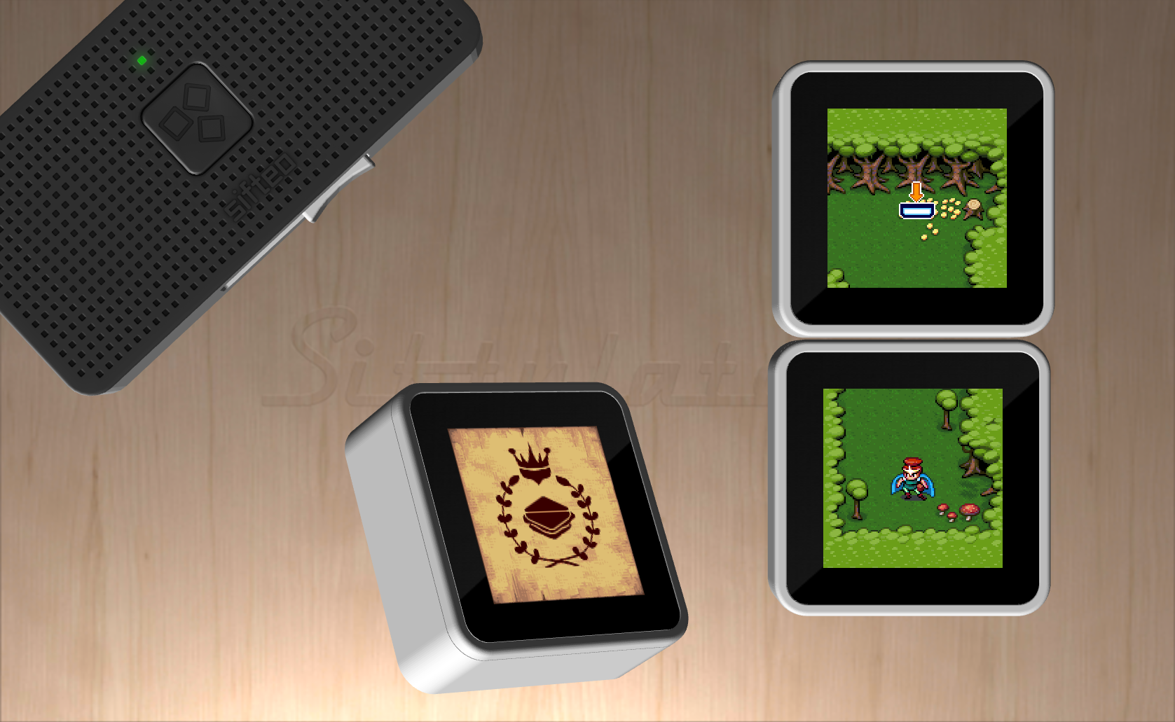
How we built a Super Nintendo out of a wireless keyboard
This is a guest article I wrote for Adafruit, on the story of how we built the hardware behind the new Sifteo Cubes, our second generation of a gaming platform that’s all about tactile sensation and real, physical objects.
-
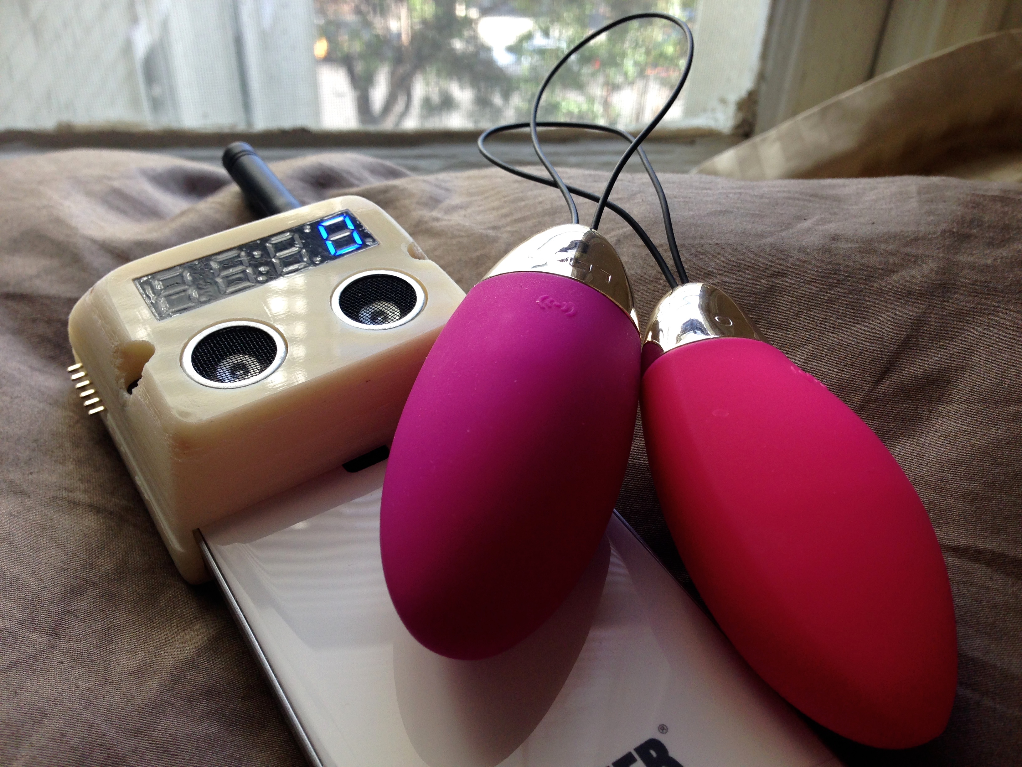
Hacking My Vagina
To me, a good sex toy helps form feedback loops. It doesn’t get in the way. A good toy gives you simple ways of exchanging signals with a partner or with your own body. It acts as a conduit. A good sex toy is analog.
-
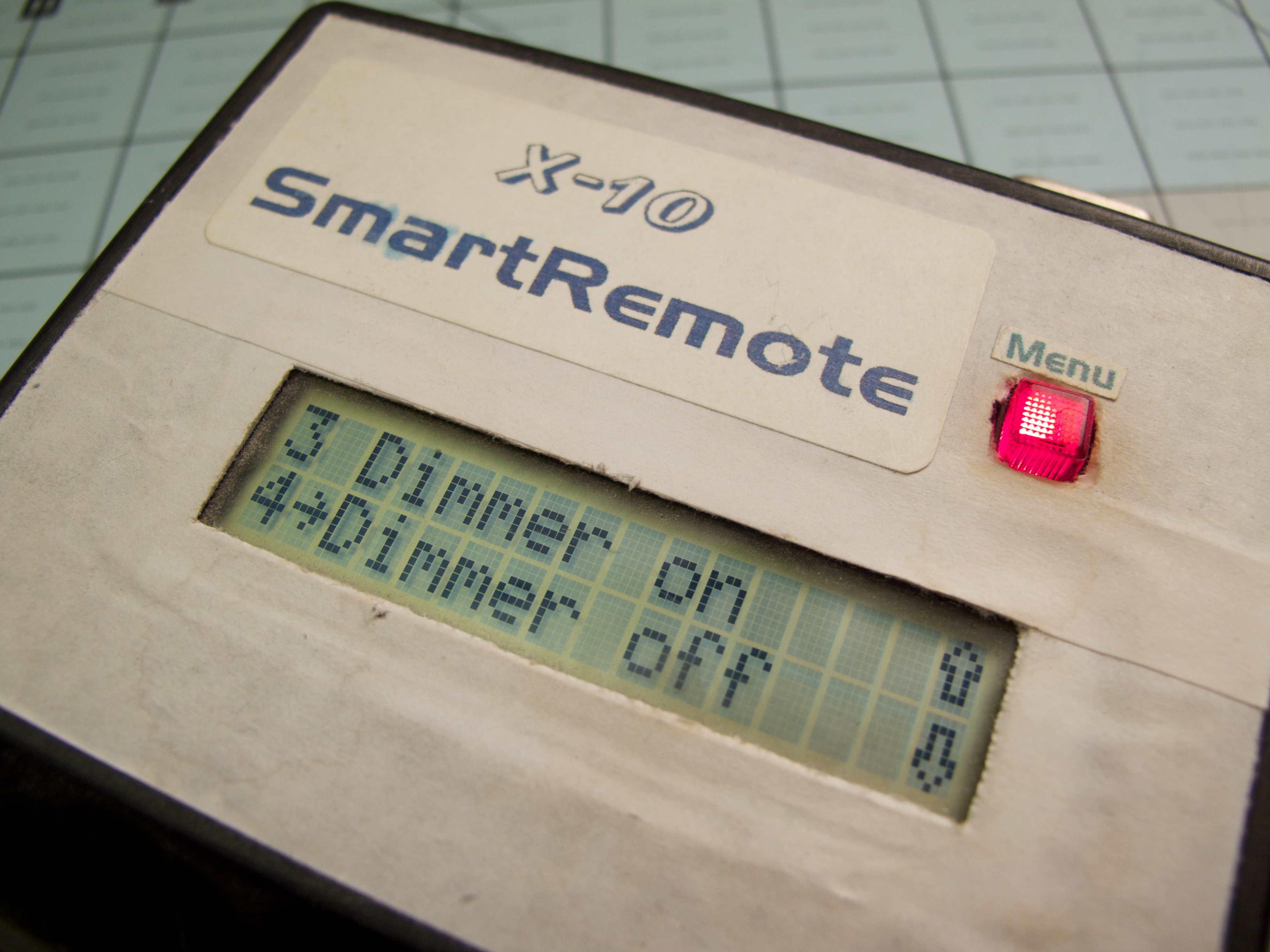
X-10 SmartRemote
I’m not even sure why I built this at all. I guess I did always have a childhood fascination with making things that seemed professional in some way. A simulacrum of some expensive piece of A/V equipment, or simple computer games that came in a shoe box with construction-paper cover art. This is another ancient…
-
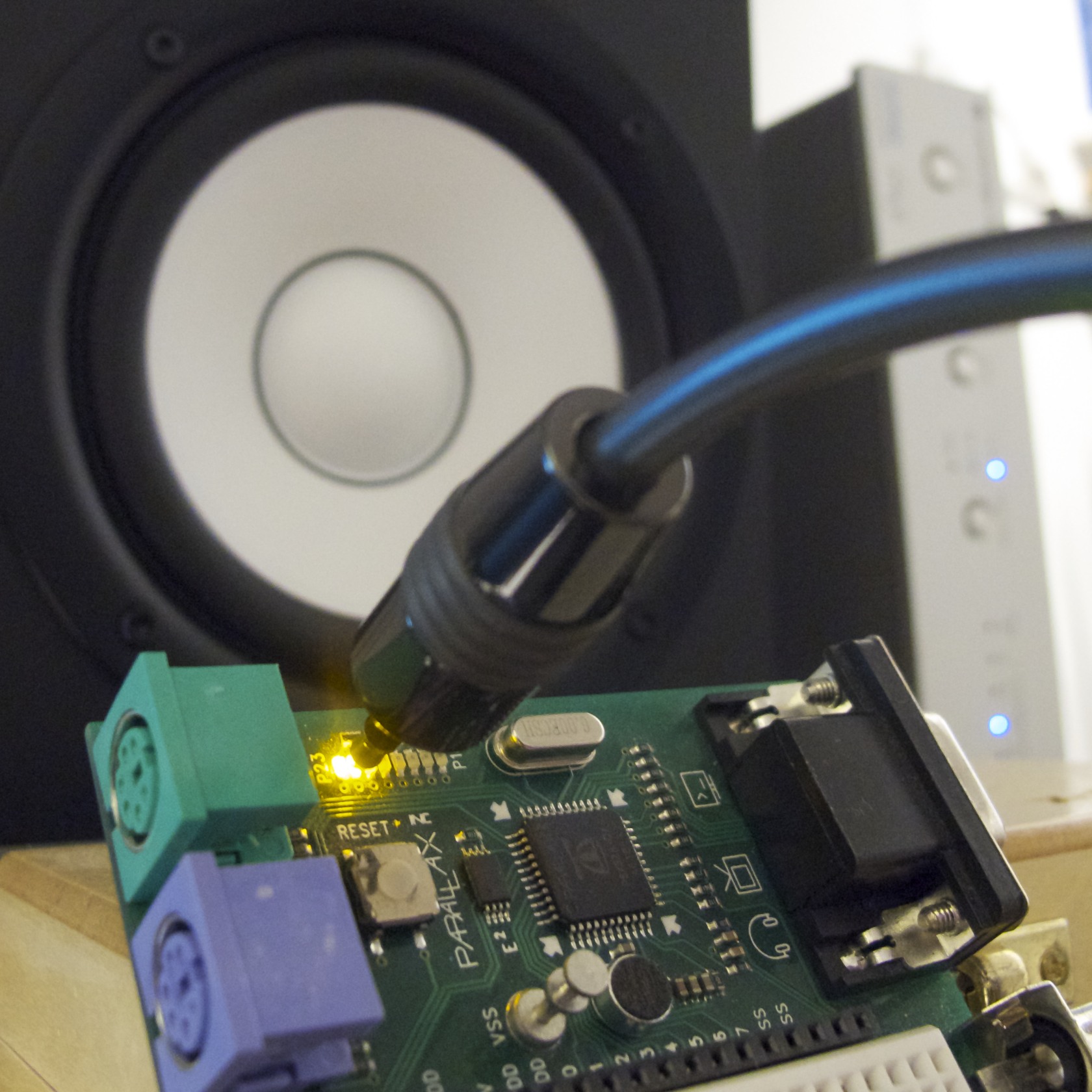
S/PDIF Digital Audio on a Microcontroller
A few years ago, I implemented an S/PDIF encoder object for the Parallax Propeller. When I first wrote this object, I wrote only a very terse blog post on the subject. I rather like the simplicity and effectiveness of this project, so I thought I’d write a more detailed explanation for anyone who’s curious about…
-

Cube64 GameCube to N64 Adaptor
Enjoy retro N64 games, but can’t stand the controller? That’s the situation I found myself in about 7 years ago, back in 2004. So I built an adaptor, to use Game Cube controllers on the N64. (tl;dr… Cube64-DX on Google Code) The adaptor hardware is very simple- all you need is a PIC microcontroller. I…
-

Turbulence
For anyone who hasn’t already seen it, Linus Akesson (of Craft fame) just released his first demo for the Parallax Propeller: Turbulence. You can watch the high resolution video on capped.tv, with an introduction by Linus himself. Or, if you have a Propeller board, he’s provided binaries and source code. The demo is quite impressive,…
-
Open source extra-sensitive high resolution TED receiver
Previously on the bloggy blog, I posted a few of my projects related to home data acquisition and to The Energy Detective (TED), a whole-house power measurement device. I made a set of homebrew wireless temperature sensors that display graphs on a digital picture frame, I reverse engineered the TED protocol, built a small self-contained…
-
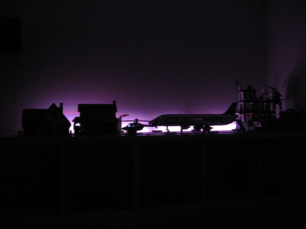
Lego Sky
Over the weekend, I had a chance to finish up a project that I started (and immediately became distracted from) several weeks ago. In our house, Paul and I have a game room. This is where the video games live, as well as other assorted geekery. We have Magic cards, D&D books, some manga.. it’s…
-
Self-contained TED receiver
My previous entry introduced a homebrew receiver for the powerline-based data protocol used by The Energy Detective. I just designed a second revision of that receiver. This one is self-contained: It gets power and modulated data from a 9V AC wall-wart transformer, and decoded data leaves via an RS-232 serial port at 9600 baud. Best…
-
Interfacing with The Energy Detective
I recently bought The Energy Detective (TED), a pretty inexpensive and friendly way to keep tabs on your whole house’s electricity usage. It’s a lot like having a more featureful version of your utility company’s power meter, sitting on your kitchen counter. It can estimate your utility bill, and tell you how much electricity and…
-
Using an AVR as an RFID tag
Experiments in RFID, continued… Last time, I posted an ultra-simple “from scratch” RFID reader, which uses no application-specific components: just a Propeller microcontroller and a few passive components. This time, I tried the opposite: building an RFID tag using no application-specific parts. Well, my solution is full of dirty tricks, but the results aren’t half…
-
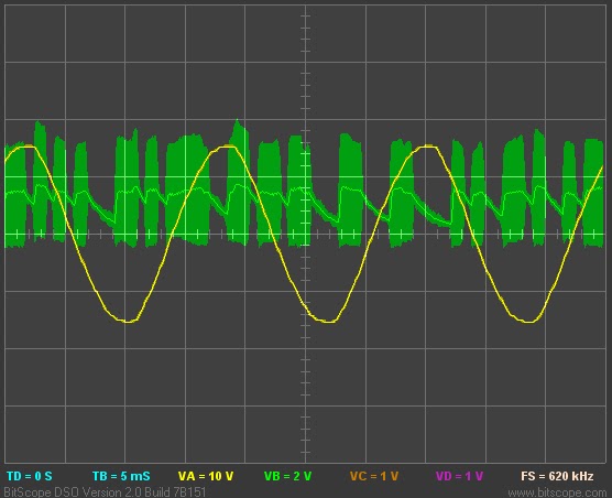
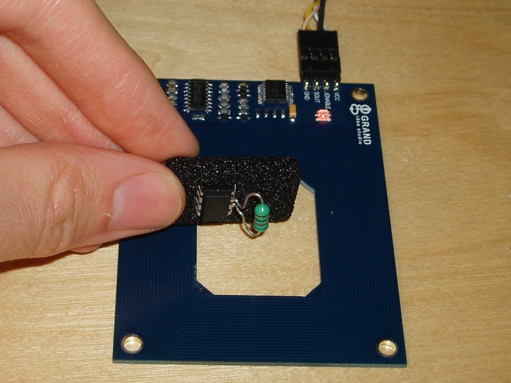
Simplest RFID reader?
That’s a Propeller microcontroller board with a few resistors and capacitors on it. Just add a coil of wire, and you have an RFID reader. Here’s a picture of it scanning my corporate ID badge, and displaying the badge’s 512 bits of content on a portable TV screen: If you’re into that sort of thing,…
-
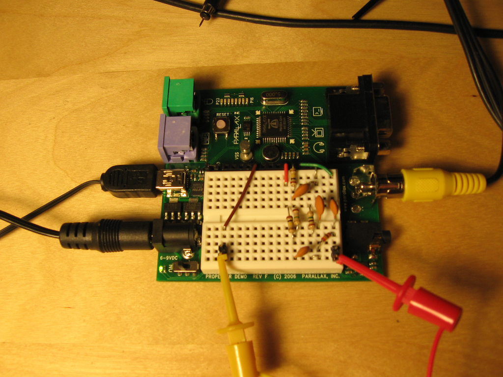
Propeller chip + SPDIF = ???
So, kind of on a random whim, I decided to build a software SPDIF encoder for the Propeller chip. It was an interesting challenge, and the results are pretty cool, but now I have no idea what do do with it. Not an uncommon problem for me, I guess… Maybe I’ll give my Propeller board…
-
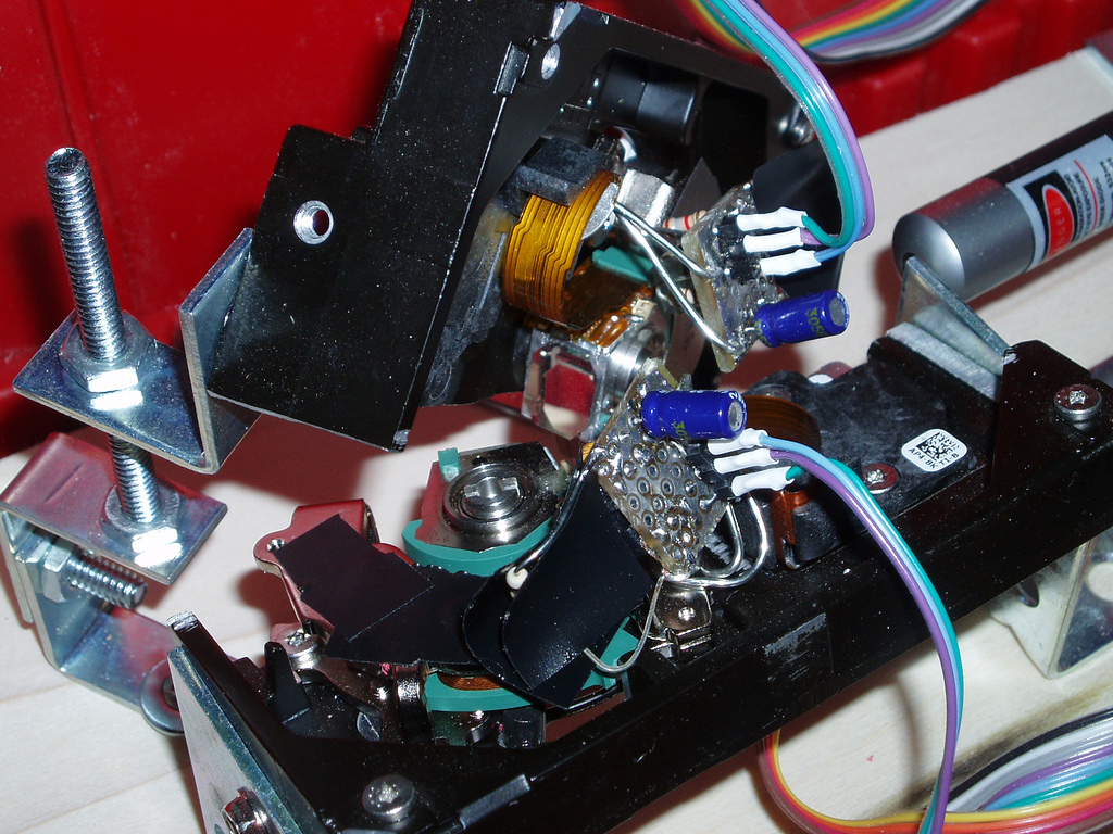
Hard disk laser scanner at ILDA 4K
I should have blogged about this long ago, as I’ve been working on it off and on for about three months now, but today I reached an arbitrary milestone that compels me to post 😉 I’m still actively working on this project, so I’ll try to make updates occasionally, and if I end up putting…
-
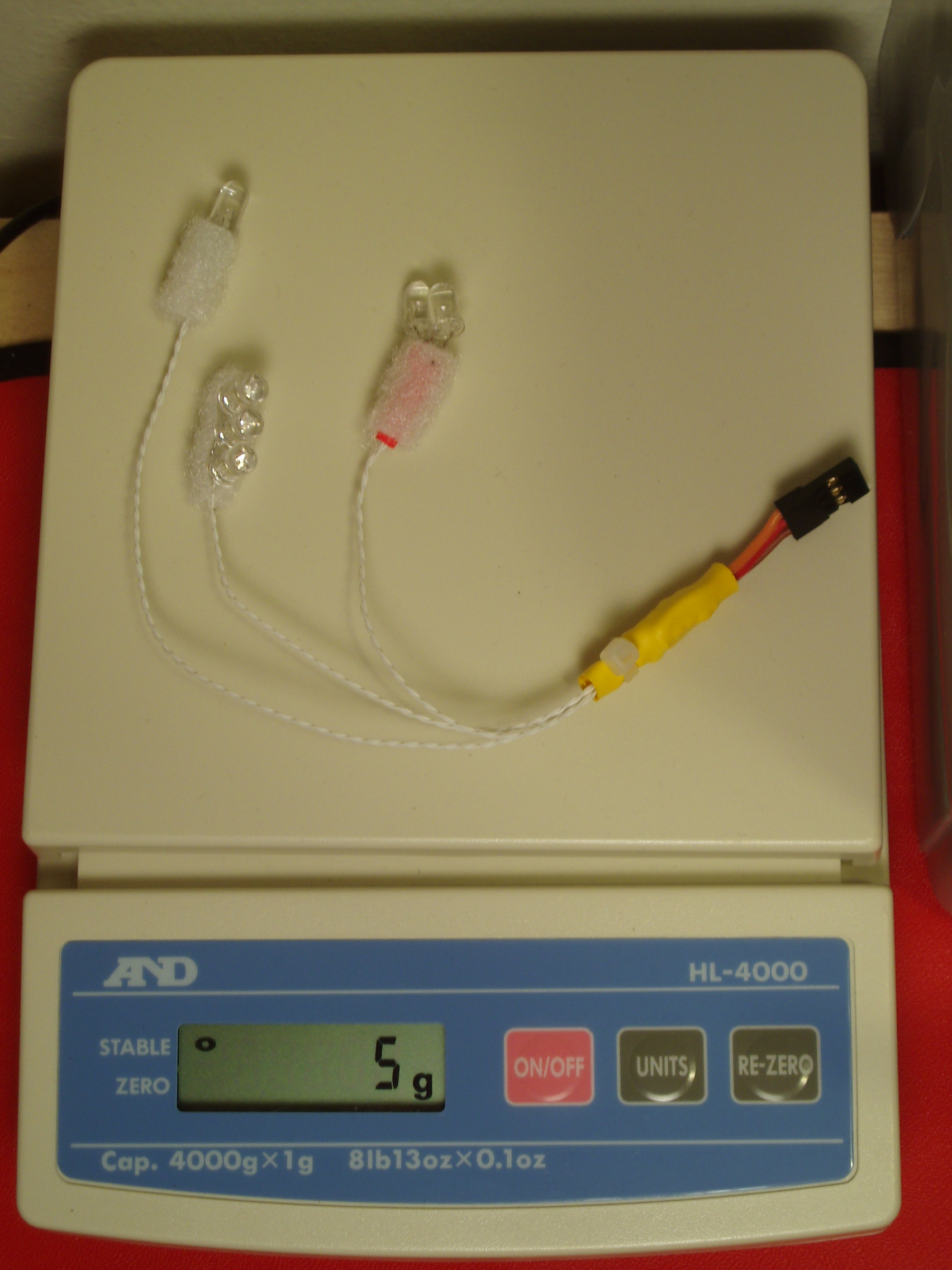
R/C helicopter lights, Revision A.5
Atmel is going to personally revoke my electrical engineering license if they ever find out what’s in that yellow heat-shrink blob, but I now have a shiny new 5 gram version of my helicopter light kit =D This version has all the same remote-control dimming and strobe capabilities of the heavier Revision A. The only…
-
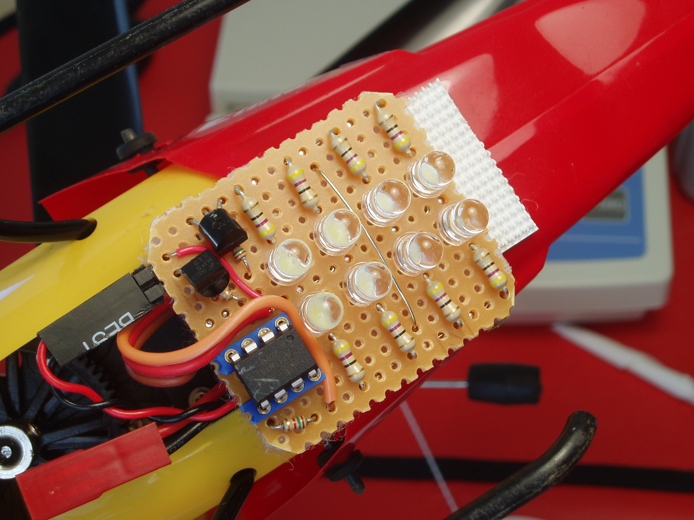
Hardware sketch: R/C helicopter light kit
As great as it is to finish a professional-looking hardware project with optimum component choices and full design documentation, I love the feeling of sketching in hardware (or as I’ve called it in the past, improvisational electrical engineering). Despite all the faults and rough edges in today’s development tools, we do live in a world…
-
Playstation controller extender
The little hardware project I started almost 2 months ago is finally done. Completely finished. Bug free! Well, almost. It is, however, in a fully assembled state with firmware that is actually pretty usable. The Unicone2 is the result of my mini-quest to extend Playstation 2 controllers over long lengths of cat5 cable. A while…