Tag: assembly
-
scanlime028 – Four Winches
Continuing our Tuco Flyer robotic camera project, this montage covers the remaining electronics assembly and bot calibration to get our winches flying a 1.5kg spool around the shop! Music for this episode is “Something Elated” by Broke For Free, licensed under CC BY 3.0, remixed slightly. Please consider supporting me on Patreon so I can…
-
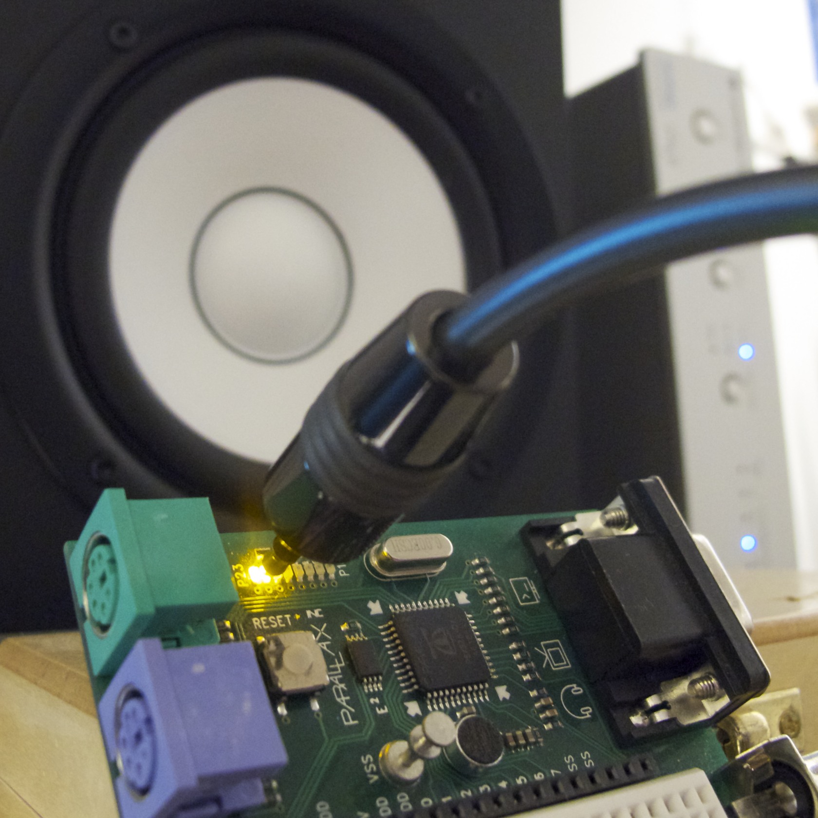
S/PDIF Digital Audio on a Microcontroller
A few years ago, I implemented an S/PDIF encoder object for the Parallax Propeller. When I first wrote this object, I wrote only a very terse blog post on the subject. I rather like the simplicity and effectiveness of this project, so I thought I’d write a more detailed explanation for anyone who’s curious about…
-

A Binary Patch for Robot Odyssey
Robot Odyssey is one of the games that I have the fondest childhood memories of. It’s both a high-quality educational game, and a gentle (but very challenging) introduction to digital logic. There’s a Wikipedia article on the game. There’s also DroidQuest which is a Java-based clone of Robot Odyssey. The DroidQuest site also contains some…
-
Real mode to protected mode inside the timer ISR
This rocks: metalkit/lib/bios.c It’s the insane little trampoline I wrote last year in order to make real-mode BIOS calls from my toy protected mode OS, Metalkit. It’s full of all kinds of awesome and scary things. So today, I just had occasion to try making a BIOS call from inside the timer interrupt, and it…
-

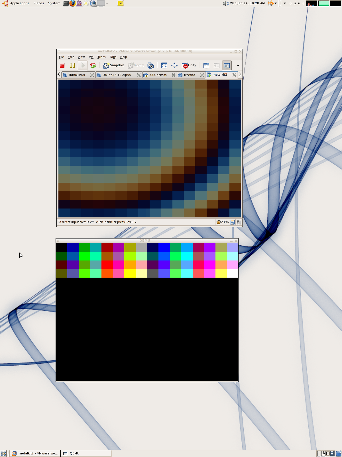
Introducing Metalkit
Metalkit is another of my random side-projects. It’s a very simple library for writing programs that run on IA32 (x86) machines on the bare metal. It isn’t an operating system, but it does contain some of the low-level pieces you might use to create one. I created it partly for fun and for the challenge,…