
People all around the internet have been doing cool things with the Wii peripherals lately, including the Wii Fit balance board. Things like controlling robots or playing World of Warcraft.
But what if you just want one weight sensor, not four? The balance board starts to look kind of pricey, and who wants to deal with Bluetooth if you don’t have to?
I’ve had a couple ideas for problems that could be solved by a cheap interface to the weight sensor in a common digital bathroom scale. The kind you can get for $15 or so at the local big-box store. For example, I’ve pondered using a grid of bathroom scales as an input device. You could use it to emulate a DDR pad, and there might be new applications that could benefit from analog weight readouts on each square of the pad.
The other idea is really Scott’s doing. He has a kegerator, and naturally we’ve been plotting to fill it full of all manner of sensors, actuators, and RFID readers. We’d like to have a continuous measurement of the keg’s weight, both to have some advance warning that it’s getting low, and to detect when an individual glass of beer has been dispensed. It seemed like if we could use the sensor from a digital bathroom scale, the filtered output would probably be accurate enough to detect the difference in weight from just one beer.
I’ve seen other projects to hack a digital scale. For example, this SD Card Bathroom Scale project uses a microcontroller to ‘read’ the LCD by decoding the signals used to drive it. This was a great idea, and he pulled it off quite well. But it requires a lot of wiring, and you’re still limited to the resolution and functionality of the original scale. I wanted to see if there was a simpler and lower-level way to hack a typical bathroom scale. And, for my particular scale at least, there is.
How a digital scale works
Old-skool analog scales (you know, with the needle that moved) were based on some clever gears and levers that converted pressure on the scale into compression of a big spring, then the spring’s compression into rotational motion that could drive a dial. But digital scales don’t really have any moving parts. They are mechanically designed to distribute your weight evenly to a bar or collection of bars which bend very very slightly under the pressure. Those bars are bonded to an electrical element that also flexes very very slightly, changing its electrical resistance. This is a strain gauge.
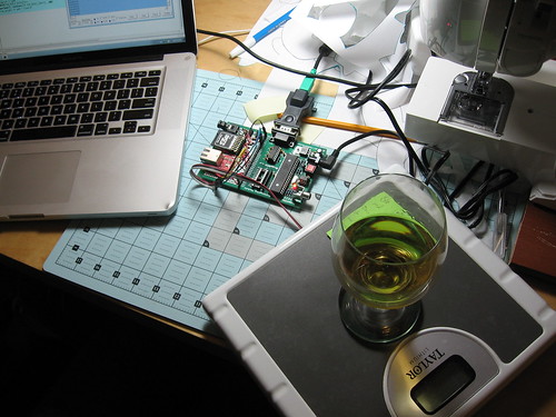
Inside the scale I hacked, you can see the two load-bearing bars. Each bar has two strain gauge sensors bonded to it. Measuring the difference in strain between the two sensors can tell you how much the bar is flexing.
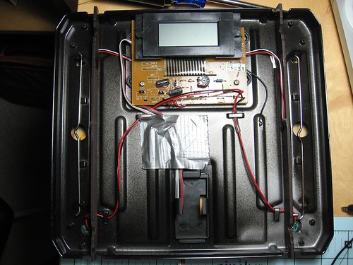
There are a lot of notable parts here:
- There are two buttons mounted on the scale’s feet. These are connected in parallel. If either one is pressed, the scale will power on.
- The vertical bars on the left and right are load cells, the mechanical parts that are designed to bend slightly. Each one has a tiny PCB with two strain gauge sensors. The two sensors share one common wire, so there are three wires going to each load cell.
- The clip in the bottom-center originally held a lithium coin cell battery.
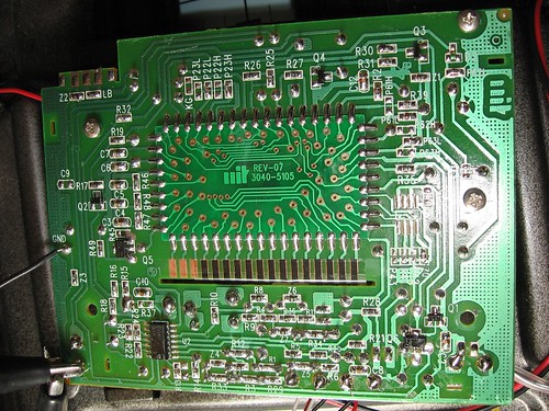
And on the main PCB:
- A numeric LCD module, bonded to the PCB.
- A microcontroller or ASIC of unknown variety. This is the digital chip that runs the scale- it’s a chip-on-board module which is soldered to the back of the main PCB.
- Analog front-end. This consists of an LMV321 quad op-amp, a few transistors, and a heaping spoonful of passives. This amplifies and conditions the signal from the strain gauge sensors. I’ll talk about this more below.
- Power switching. The analog front-end is very low-power, but to preserve battery life even more, the microcontroller uses a transistor to turn it off entirely when the scale is sleeping.
- Hidden features! There’s a “CAL” header. If you short this header, wake up the scale, then un-short it, the scale will go into a factory calibration mode. The LCD displays some kind of raw reading in this mode, and it continuously updates.
This is the only scale I’ve disassembled, so your mileage may vary. If your scale puts everything on a single IC, there may not be a way to hack it without building your own analog front-end. But if you get lucky (older scales may be more likely to use discrete parts) you may see something like this in the scale you disassemble. The separation of functionality into discrete analog and digital circuits makes this model of scale quite fun and easy to hack!
Reverse Engineering
This section will explain the process I used to figure out how this scale works. You might be able to use some of the same procedures on other types of digital scales.
- Visual inspection: Noticed the op-amp chip, arrangement of the passives, how the strain gauges were connected, power switching.
- Looked up a data sheet for the op-amp chip. Noted the power and output pins.
- Used an oscilloscope to probe each of the four op-amp outputs, looking for a signal that seemed plausible for a microcontroller to measure. This would have to be either a fairly high-amplitude DC analog voltage, or some kind of variable-frequency signal.
- Found this signal. Output D on pin 14 had three different kinds of waveforms: low when the scale is off, high when the scale is on but not actively measuring weight (microcontroller is doing calculations or updating the LCD?). When weighing, this pin is a pulse train whose duty cycle seems proportional to weight.
- Traced this signal back to a pin on the microcontroller.
- At this point, it might have been sufficient to interface to the scale by snooping this signal. But the pulse train is not present all of the time, so I’d have to have extra code to ignore the idle periods. And you’d have to simulate button presses to keep the scale awake. So, I wanted to figure out how to keep the scale in measurement mode all the time.
- First step: Keep the analog front-end powered on. I traced the V+ pin on the op-amp back to a transistor that the microcontroller uses to power on all analog circuitry. I soldered a shorting jumper across this transistor.
- Now when the microcontroller is off, the op-amp output is high rather than low. This means there must be some other signal that the microcontroller is outputting in order to put the analog frontend into measurement mode, or otherwise generate that pulse train.
- Probed around the microcontroller with my oscilloscope, looking for interesting signals on the pins nearby where the op-amp signal enters.
- Found another pulse train which was active only when the scale was in weighing mode. This signal seemed to be at the same frequency as the op-amp output signal. This one is normally low, but has brief high pulses.
- At this point, I thought I had enough information to guess how the circuit worked. Traced where this signal goes, to verify. It is an output from the microcontroller which heads to a transistor in the analog front-end. I didn’t fully reverse engineer this, but I suspect it’s discharging a capacitor that’s used for integrating the analog weight signal.
- Made the modifications discribed below, and hooked the analog front-end input and output up to a Propeller microcontroller. Verified my guesses by performing some experiments with the microcontroller.
Analog Front-end
This documents my understanding of how the analog front-end works in this digital scale. I didn’t reverse engineer the circuit itself, so this is really just a “black box” description based on observing how the circuit behaves.
The circuit’s input is a tiny resistance from four strain gauges. They are arranged as two independent load cells, each with two sensors that act as a differential pair. The front-end amplifies these tiny differences in resistance, and sums them into a single analog signal. For example, if the strain gauges were labeled L1, L2, R1, and R2 (two sensors each for left and right load cells), the analog summation would be:
Total = L1 – L2 + R1 – R2
This total is still an analog signal, and it’s fairly noisy. There would be a lot of different ways to convert this to a digital signal: a standard successive-approximation A/D converter, a voltage to frequency converter, an RC oscillator… This scale uses an approach that’s simple, cheap, and pretty accurate for situations where you’d like to dynamically make tradeoffs between sample rate and accuracy. It uses an integrator and comparator.
In this approach, there is a capacitor which can charge or discharge depending on the state of a signal from the microcontroller. I’ve been calling this the “Reset” signal. When Reset is low, the capacitor slowly charges at a rate which depends on the analog Total above. This is an analog integrator. When Reset is high, the capacitor discharges quickly. This voltage across the capacitor is fed to a comparator, where it’s compared to a reference threshold. If it’s larger than this threshold, you get a logic “1” out, if it’s smaller you get a logic “0”.
This starts to look a lot like a closed-loop feedback system. In fact, you can even think of it as an electronic equivalent to the old mechanical balance. Instead of balancing two physical weights on a lever, you’re balancing two electric currents which are trying to charge or discharge the integration capacitor. If the capacitor voltage is too high, you need to drain it a bit. If it’s too low, you need to let if fill up. If you keep the capacitor voltage oscillating right around the comparator threshold, it’s just like you’ve balanced a mechanical scale. Now you know how heavy the object you’re weighing is, because you know how much time you need to spend discharging the capacitor to keep it balanced.
I find this symmetry between the mechanical and electrical scale pretty elegant. It’s also practical- your accuracy is limited by electrical or mechanical noise in the circuit, and by your microcontroller’s timing resolution. But you can always integrate over longer periods of time in order to trade sample rate for accuracy. If you keep the capacitor balanced for a whole second, and add up how much time you spent discharging the capacitor over that second, you’ve just calculated the average weight with much more precision than you’d have if you measured the length of a single discharge pulse.
Modding the Scale
After figuring out the analog front-end, I really just wanted a way to use that by itself without worrying about the built-in microcontroller or LCD. This turned out to be really easy:
- Remove the lithium battery and holder
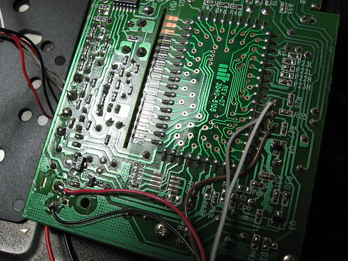
- Solder a jumper wire across the transistor that normally powers off the analog front-end. (This is visible in the photo below, near the red and black power wires.)
- Cut three traces near the microcontroller: Reset signal out, comparator signal in, and button signal in. This separates the microcontroller from the analog circuitry, and it also prevents the microcontroller from waking up. It will stay turned off.
- Solder a 5-pin ribbon cable to the board: Ground, Power (+3v), Buttons (optional), Reset out, Comparator in.
The wires on the left are power and ground. It’s hard to see here, but the traces corresponding to the three wires on the right were cut, between the wires and the chip-on-board assembly. From top to bottom, those wires are comparator, button, and reset. And that’s it! With that simple mod, the scale is ready to connect directly to any 3.3v microcontroller with two free I/O pins. I used a Propeller, but an AVR should work great for this too. If you’re using a 5V microcontroller, you’ll still want a 3v or 3.3v power supply for the scale. You may also want to limit the voltage on the reset output signal too, though I suspect this isn’t actually necessary.
Software
I tested this mod using a PropRPM board and some jumper wires. All of the other stuff on the PropRPM board is unrelated to this project- no external components are necessary to talk to the scale, just two 3.3v I/O pins.
The software is pretty simple. To measure weight, you need to toggle the “Reset” output on and off in order to keep the integration capacitor balanced around a comparator threshold. Pulling Reset high will quickly drain the capacitor, pulling it low lets the capacitor charge at a rate which depends on the total weight on the scale. You can take more accurate measurements by repeating this for more cycles, or take quicker measurements by repeating it for fewer cycles. On the Propeller, I use the system clock to measure the total amount of time that I spend letting the capacitor charge. Here’s a complete program that prints scale measurements to the serial port:
CON
  _clkmode = xtal1 + pll16x
  _xinfreq = 5_000_000

  PIN_SCALE_OUTPUT = 3    ' Pulse high to discharge
  PIN_SCALE_INPUT = 4     ' Output from integrator

OBJ
  term : "Parallax Serial Terminal"

PUB main
  term.start(115200)
  repeat
    term.Str(String(term#NL))
    term.Dec(measure_raw(500))

PRI measure_raw(period) : raw_weight | timeref
  raw_weight := 0
  repeat period

    ' Reset, and wait for input to go high. This is its idle state.
    OUTA[PIN_SCALE_OUTPUT]~
    DIRA[PIN_SCALE_OUTPUT]~~
    waitpne(0, constant(|< PIN_SCALE_INPUT), INA)

    ' Turn off the 'reset' output. This starts integrating
    ' the pressure. When the analog integrator reaches a threshold,
    ' our input pin goes high. Time this.
    timeref := cnt
    OUTA[PIN_SCALE_OUTPUT]~~
    waitpeq(0, constant(|< PIN_SCALE_INPUT), INA)
    raw_weight += cnt - timeref
And that’s all it takes! I’m looking forward to trying this with a larger grid of scales. A powerful microcontroller like the Propeller should be able to simultaneously sample and filter measurements from several scales. This proof-of-concept looks pretty promising for the kegerator project, too. With an integration time of a second or so, it can easily measure weight accurately enough to count glasses of beer 🙂
P.S. I’m pretty sure I just spent more time writing this blog entry than I spent on the hack itself. How silly is that?