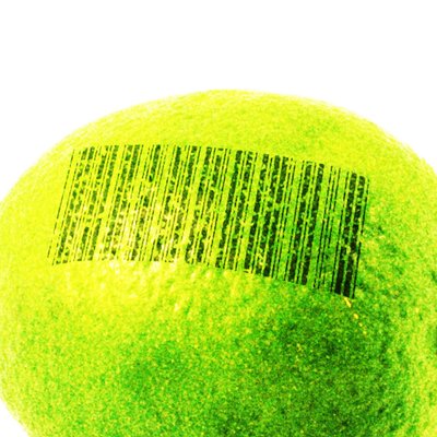

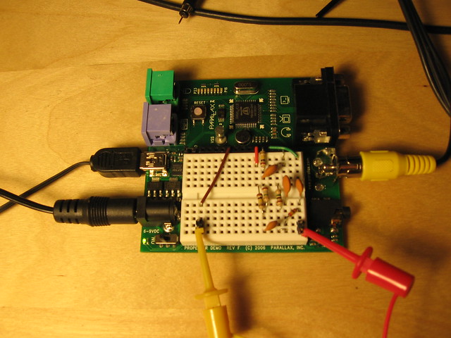
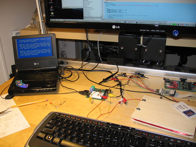
That’s a Propeller microcontroller board with a few resistors and capacitors on it. Just add a coil of wire, and you have an RFID reader. Here’s a picture of it scanning my corporate ID badge, and displaying the badge’s 512 bits of content on a portable TV screen:
If you’re into that sort of thing, I wrote a forum post with technical details and pretty oscilloscope screenshots.
Update: The forum link went dead for a while when Parallax switched to a different forum server. I’ve updated the link, but just in case.. A copy of the post is included below.
I’ve been interested in building an RFID reader for a crazy project a friend of mine is working on (automated beer dispensing system 😉 and it was an excuse to do some analog tinkering, so I had a go at building an RFID reader with the Propeller. Why not use Parallax’s fine RFID reader accessory? I wanted to be able to read any off-the-shelf card, including common proximity ID badges.
I just got it working. I’d love to be proved wrong, but as far as I know this is the world’s simplest RFID reader design:
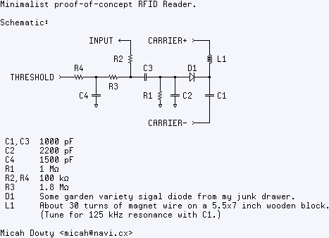
Edit: All capacitances are in picofarads. C1 and C3 should be 1000 pF, not 1000 nF. Likewise, C2 is 2200 pF.
Yep.. just a propeller and a few passive components. To understand this circuit, it’s helpful to know how RFID works first. Here’s the 10-second RFID primer for those who aren’t already familiar with it:
RFID tags work via magnetic fields, like a transformer. A coil in the reader generates a magnetic carrier wave, which is picked up by a coil in the tag or card. This carrier wave powers the card, and provides it with a clock reference. To send data, the card varies the amount of current it draws from the reader’s field, attenuating the carrier wave slightly. This attenuation is usually used to send some kind of modulated signal. The card I’ve been testing with uses a 125 kHz carrier wave, and FSK (Frequency Shift Keyed) modulation. Zeroes and ones are attenuation waveforms with different frequencies.
So, step one: generating a carrier wave with the propeller. I use a counter, naturally, and I generate a differential-drive signal on two pins. This gives me 125 kHz at about 6.6V peak-to-peak. I use an LC tank tuned near 125 kHz to amplify this and shape it into a sine wave. Here’s my carrier wave, measured at the junction between L1 and C1. Note the scale- it’s about 20 volts peak-to-peak! (Also notice that my tuning isn’t quite perfect. Sadness and despair!)

When you bring a proximity card near the reader coil, you can see the attenuation waveform overlaying the carrier wave. This is at the same voltage scale, measured at the same point, but I zoomed out on the X axis so you can see the pattern clearly:

To detect this signal, I use D1, C2, and R1 as a peak detector and low-pass filter, to remove the majority of the high-voltage carrier wave. This is then AC coupled via C3. At this point, the left side of C3 has a “floating” low-voltage waveform that I can position anywhere I want, by changing the bias on C3.
To generate this bias voltage, I use CTRB in DUTY mode. I’ll explain why I call this pin “threshold” later. R4 and C4 are a low-pass filter give me an analog output voltage from CTRB. This signal is usually DC- it’s used for calibration.
R3 “pulls” the floating waveform toward the analog value output by CTRB. Now I take advantage of the Propeller’s Vdd/2 input threshold, and use the “input” pin as a comparator. (R2 is just to limit high-frequency noise.) Now I can use the CTRB voltage to adjust the detection threshold- how much attenuation causes “input” to read 0 vs 1.
Now I have a digital signal, but it’s still really noisy. I use an assembly-language cog to reject as much noise as possible, and time the resulting FSK pulses. This image shows the analog signal at the junction between R2 and C3, along with the digital pulse detector’s output. The amount of time between pulses signifies a “1” or “0” bit. In this case, the detection threshold is at 9 carrier wave cycles. Less than 9, it’s a 0. More than 9, it’s a 1 bit.

End result: I can display the 512 bits of data from my corporate proximity badge. Neat.
I’d include more details on the actual data I’ve captured and the protocol, but so far I’ve only been able to test this with a couple ID badges from the office and I’d rather not share those bits 😉 I have a Parallax RFID starter kit on order, so I’ll let you know if I can read any of those tags successfully.
Source code is attached, but be warned it’s hugely messy.
Update: The latest code and schematics are now have a home in the Object Exchange: https://obex.parallax.com/object/549.