As great as it is to finish a professional-looking hardware project with optimum component choices and full design documentation, I love the feeling of sketching in hardware (or as I’ve called it in the past, improvisational electrical engineering). Despite all the faults and rough edges in today’s development tools, we do live in a world now where it’s easy turn an idea into a working prototype with very little time and money.
Flying in the dark
Yesterday’s hardware sketch was a light system for my helicopter, an E-Flite Blade CX2. I wanted:
- A way to fly at night. Real navigation lights would be nice, but for starters I just want the whole helicopter body to glow.
- A way to take off and land safely. I’ve flown with only a body light before, and it’s really hard to land when you don’t know quite where the ground is.
- A bright strobe, for extra visibility and attention.
- A way to control the lights remotely, using the extra servo channel on the Blade CX2’s radio.
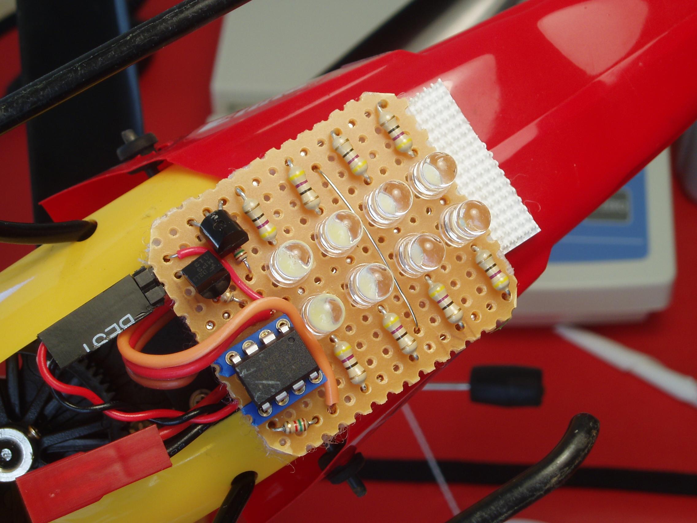
My finished prototype takes the form of a small circuit board that attaches under the canopy with velcro. That board holds the light control electronics, plus a bright white searchlight. It connects to the radio (for power and control) and to the internally-mounted body lights. The body lights are just bare LEDs attached to the inside of the tail and canopy with velcro. One white LED in the tail, one red and one yellow LED in the canopy.
Both sets of lights have full brightness control using a single knob on the BCX2’s transmitter. At the knob’s minimum setting, all lights are off. As you turn it up, first the body lights fade on. Next, the searchlight fades on. Just before hitting the maximum setting, all the lights are on at full brightness. If you turn the knob farther, to its maximum, the searchlight goes into strobe mode.
There are some rough edges, but it works remarkably well for such a simple design. The total weight is about 15 grams. It’s heavier than I’d like, but it doesn’t effect flight performance much. I’d still like some orientation lights mounted on the skids or the sides of the control PCB, but the body light is pretty easy to fly by. The searchlight is incredibly visible at maximum brightness. Even from an altitude of 50 feet or so, the light casts a bright spot on the ground.
Technical details
Skip this section unless you’re a huge dork ;)
The light controller uses an Atmel ATtiny85 microcontroller (kind of overkill) and a pair of NPN Darlington transistors to drive the LEDs. The microcontroller’s firmware (navi-misc/rc/light-dimmer/main.c) is quite simple. An assembly-language loop times the pulses coming in from the radio, then the firmware decides on a corresponding lighting mode and sets up the AVR’s hardware PWM peripheral accordingly.
This hardware sketch was built with whatever parts I had handy. The LEDs are low-tech by today’s standards, the microcontroller was kind of overkill, and MOSFETs would have been better than the Darlington transistors. If I were building a second revision of this, I’d make a few improvements:
- All surface-mount parts and a PCB, to decrease size and weight.
- Use a single 1-watt Luxeon LED instead of an array of cheapo white LEDs.
- To drive the Luxeon LED, I’ll probably want a simple buck converter.
- Logarithmic LED brightness control, rather than linear.
- Side-emitting navigation lights, mounted directly on the main PCB.
- Optimize the firmware for low-power operation when the lights are off. Right now it costs about 8mA to run the AVR in its pulse-detecting loop at 8 MHz.
- Start mass-producing and selling these ;) It’s much better than any commercial light kit I’ve seen for the Blade CX2, and the parts are quite cheap.
/*
 * Simple R/C light dimmer.
 *
 * This connects two brightness-controlled LEDs to a single R/C
 * servo output. From minimum pulse width to maximum pulse width,
 * we sweep through a few different modes:
 *
 *   - At minimum, all lights are off
 *   - Light 1 begins to fade on
 *   - Light 1 remains on, Light 2 begins to fade on
 *   - Lights 1 and 2 are both on at full brightness
 *   - At maximum, Light 1 remains on and Light 2 begins to strobe
 *
 * In my helicopter model, I use Light 1 as a general
 * cockpit/navigation light and Light 2 as a high-power searchlight.
 *
 * Wiring:
 *   - PINB0, servo pulse input
 *   - PINB3, Light 1 output
 *   - PINB4, Light 2 output
 *
 * This is designed to run on an 8-pin ATtiny, with the internal 8 MHz
 * RC oscillator. It was tested with an ATtiny85.
 *
 * The light outputs may be connected directly to small (40 mA or
 * less) LEDs. Larger LED loads should be driven by a MOSFET with
 * a pull-down resistor on the gate.
 *
 * -- Micah Dowty <micah@navi.cx>
 *
 */

#include <avr/io.h>

#define F_CPU         8000000UL                      // 8 MHz

#define SERVO_MS      (F_CPU / 6000UL)               // Ticks per millisecond
#define SERVO_MIN     ((uint16_t)(1.1 * SERVO_MS))
#define SERVO_CENTER  ((uint16_t)(1.5 * SERVO_MS))
#define SERVO_MAX     ((uint16_t)(1.9 * SERVO_MS))

#define SERVO_PIN     PINB0
#define PULLUP_PINS   (_BV(PINB1) | _BV(PINB2))

#define LIGHTMODE_OFF      0       // All lights off
#define LIGHTMODE_FADE_1   1       // Light 1 fading, Light 2 off
#define LIGHTMODE_FADE_2   2       // Light 1 on, Light 2 fading
#define LIGHTMODE_STROBE   3       // Light 1 on, Light 2 flashing

uint8_t pulse_counter      = 0;    // Global servo pulse counter, for low-frequency timing
#define STROBE_DIVISOR     _BV(1)  // Bit mask for dividing pulse_counter into our strobe frequency


/*
 * Wait indefinitely for a servo pulse. When the pulse arrives, time
 * it.  Returns a value in the same units as SERVO_MS.
 */

static uint16_t
read_pulse(void)
{
    register uint16_t result asm("r24");
    uint8_t temp;

    asm volatile (

	/* Zero result */
	"clr %A0 \n\t"
	"clr %B0 \n\t"

	/* Wait for SERVO_PIN to go high (Accurate to 4 clock cycles) */
	"L_1%=: \n\t"
	"in %1, %2 \n\t"
        "andi %1, %3 \n\t"
	"breq L_1%= \n\t"

	/*
	 * Until it goes low, incrment result.  As long as SERVO_PIN
	 * is high, this increments 'result' every 6 clock cycles.
	 */
	"L_2%=: \n\t"
	"in %1, %2 \n\t"         // 1 clock
	"adiw %A0, 1 \n\t"       // 2 clocks
        "andi %1, %3 \n\t"       // 1 clock
	"brne L_2%= \n\t"        // 2 clocks

	/* Outputs */
        : "=r" (result),
	  "=d" (temp)

	/* Inputs */
        : "I" (_SFR_IO_ADDR(PINB)),
	  "I" (_BV(SERVO_PIN))
        );

    pulse_counter++;
    return result;
}


/*
 * Set up outputs for a particular light mode and fade step.
 *
 * We actually control both lights with Timer1's PWM module, so we can
 * only have a single light fading at once and we need to pull some
 * tricks to ensure the non-fading light is in the correct state.
 *
 * It would have been simpler to use separate PWM compare outputs for
 * each LED, but this configuration makes in-circuit programming
 * easier :)
 */

static void
set_light_state(uint8_t mode, uint8_t fade_step)
{
    switch (mode) {

    case LIGHTMODE_OFF:
    default:
	/*
	 * Float the light output pins
	 */
	PORTB = PULLUP_PINS;
	DDRB = 0;
	GTCCR = 0;
	break;

    case LIGHTMODE_STROBE:
	/*
	 * Drive both lights, toggle Light 2
	 */
	DDRB = _BV(PINB3) | _BV(PINB4);
	GTCCR = 0;
	if (pulse_counter & STROBE_DIVISOR)
	    PORTB = PULLUP_PINS | _BV(PINB3) | _BV(PINB4);
	else
	    PORTB = PULLUP_PINS | _BV(PINB3);
	break;

    case LIGHTMODE_FADE_1:
	/*
	 * Disable Light 2 (OC1B) and fade Light 1 (!OC1B).
	 * We can't do this using the Timer1 PWM mode
	 * alone, so we need to float Light 2 using
	 * DDRB.
	 */
	DDRB = _BV(PINB3);
	GTCCR = _BV(PWM1B) | _BV(COM1B0);
	OCR1C = 0xFF;
	OCR1B = 0xFF - fade_step;
	break;

    case LIGHTMODE_FADE_2:
	/*
	 * Turn Light 1 (!OC1B) full-on and fade Light 2 (OC1B).  To
	 * do this, we disable !OC1B as a PWM output and set it high
	 * using PORTB.
	 */
	DDRB = _BV(PINB3) | _BV(PINB4);
	PORTB = PULLUP_PINS | _BV(PINB3);
	GTCCR = _BV(PWM1B) | _BV(COM1B1);
	OCR1C = 0xFF;
	OCR1B = fade_step;
	break;
    }
}


/*
 * Initialize light-related hardware.
 * This sets the Timer1 PWM frequency, and initializes I/O directions.
 */

static void
init_lights(void)
{
    /*
     * Use system clock with a 1/128 divider.  This gives us a 244 Hz
     * PWM waveform. This value might need to be tweaked to minimize
     * electrical interference on your particular model.
     */
    TCCR1 = _BV(CTC1) | _BV(CS13);

    set_light_state(LIGHTMODE_OFF, 0);
}


int main(void)
{
    init_lights();

    /* Ignore the first several pulses, to give the radio time to stabilize. */
    for (uint8_t i = 0; i < 50; i++)
	read_pulse();

    while (1) {
	uint16_t pulse = read_pulse();

	if (pulse <= SERVO_MIN) {
	    set_light_state(LIGHTMODE_OFF, 0);
	} else if (pulse >= SERVO_MAX) {
	    set_light_state(LIGHTMODE_STROBE, 0);
	} else if (pulse <= SERVO_CENTER) {
	    set_light_state(LIGHTMODE_FADE_1, ((uint32_t) pulse - SERVO_MIN) * 0xFF / (SERVO_CENTER - SERVO_MIN));
	} else {
	    set_light_state(LIGHTMODE_FADE_2, ((uint32_t) pulse - SERVO_CENTER) * 0xFF / (SERVO_MAX - SERVO_CENTER));
	}
    }

    return 0;
}