
Tag: wireless
-
scanlime:005 / Microphone Receiver
I take apart a Pyle PDWM1940 wireless microphone receiver, searching for a way to make the output less noisy. Meanwhile, I’ll be using the same receiver for filming.
-
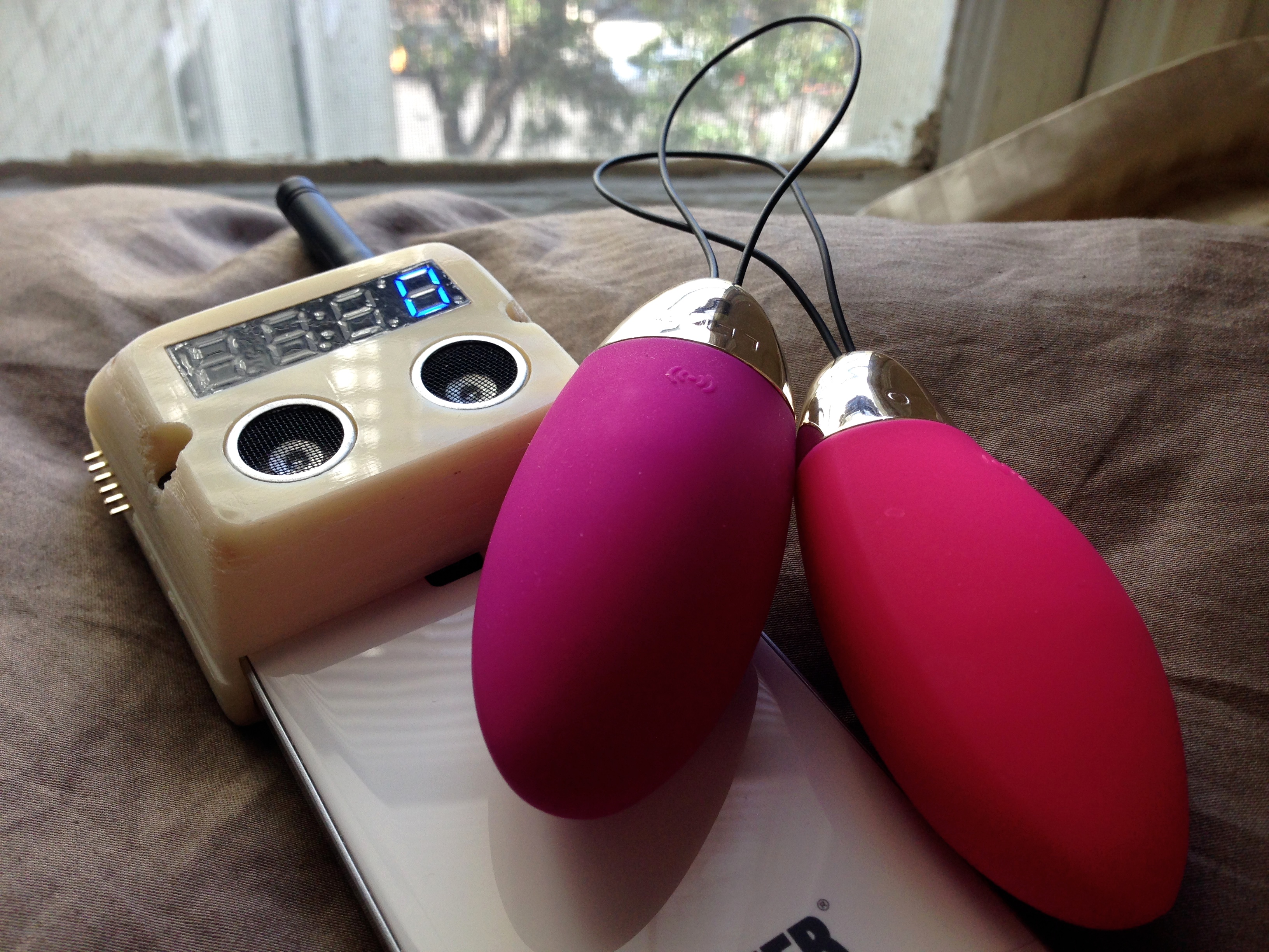
Hacking My Vagina
To me, a good sex toy helps form feedback loops. It doesn’t get in the way. A good toy gives you simple ways of exchanging signals with a partner or with your own body. It acts as a conduit. A good sex toy is analog.
-

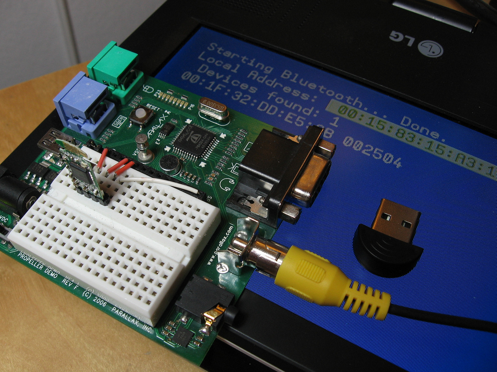
Propeller Bluetooth Stack Demo
After going months without a lot of time for working on my hobby projects, I finally had a few free days to work on debugging my embedded Bluetooth stack for the Propeller. I got it working well enough to demo a Serial Port Profile device, implemented using only a Propeller Demo Board and a $2…
-
Embedded Bluetooth for $2
This is a continuation of my experiments in bit-banging full-speed USB on the Propeller. I have the basic host controller working reasonably well now, so I started trying to do something a bit more “useful” with it by implementing a simple Bluetooth stack on top of it. Bluetooth and USB are both quite complicated, and…
-
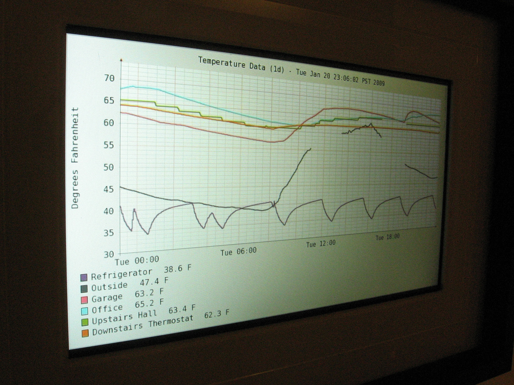
Wireless temperature picture frame mashup
This is the latest geeky addition to our home decor. It’s a Kodak W820 digital picture frame, showing a graph of real-time temperature data collected from around the house: upstairs and downstairs, garage, outdoors, and even inside the refrigerator. More photos on Flickr, implementation details below… Temperature Sensors Most of my friends probably know that…
-
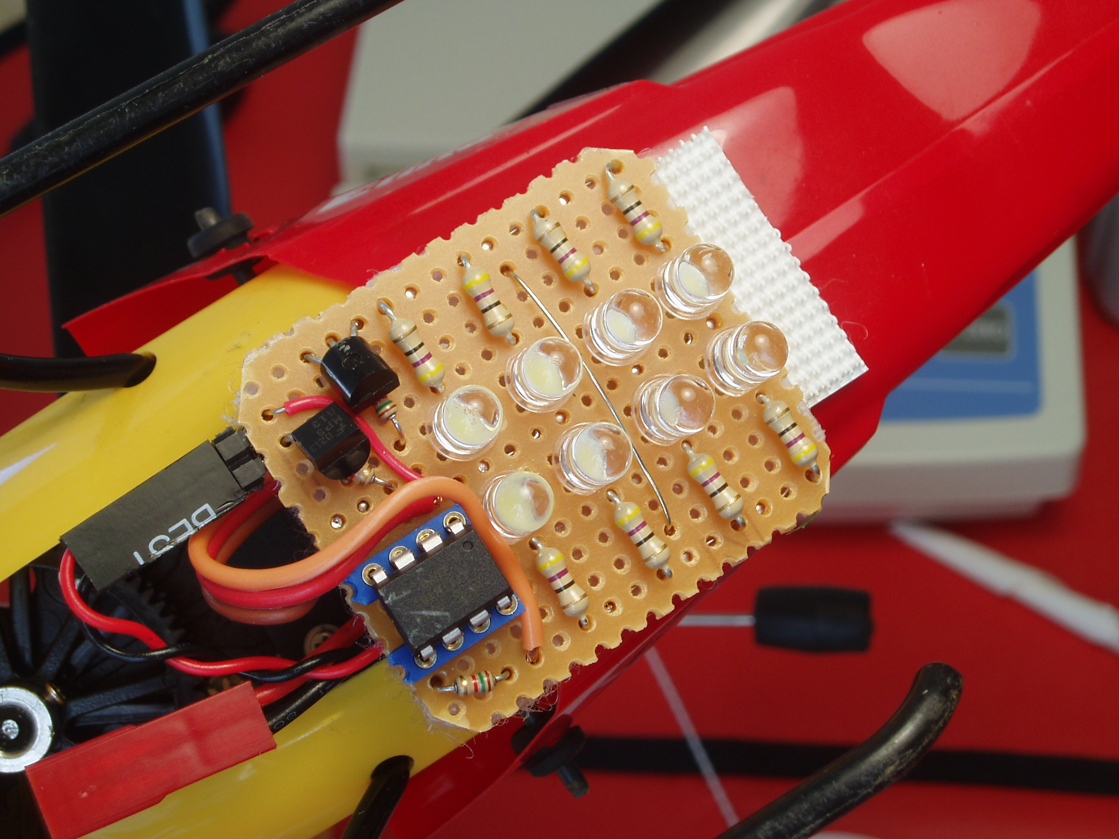
Hardware sketch: R/C helicopter light kit
As great as it is to finish a professional-looking hardware project with optimum component choices and full design documentation, I love the feeling of sketching in hardware (or as I’ve called it in the past, improvisational electrical engineering). Despite all the faults and rough edges in today’s development tools, we do live in a world…