scanlime040 – Test Jig Quick Look

I found these two test jigs for sale at a local business that was relocating. They would have been used as part of the quality assurance procedure for smart bike lights. Later we might go into more detail on the firmware, or repurpose the formidable hunks of metal for another project!

Thank you so much for watching, subscribing, and sharing my videos. And a special thanks to my supporters on Patreon, where recurring donations make this content possible.

If you’d like some of those cool scanlime stickers or Servo AF stream gear, check out the shop.

For previous episodes, check out the full scanlime playlist.

Each episode is compiled together from many livestreams which you can hang out with on the companion scanlime-in-progress channel.

Follow @scanlimelive for live streaming announcements.

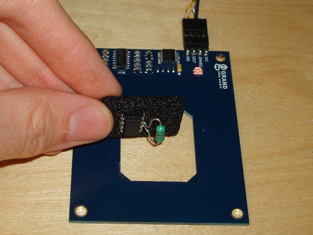
AVR RFID, Optimized and Ported to C

Way back in 2008, I posted a writeup about using an AVR microcontroller as an RFID tag. Since then, it’s been great to see many people pick up this code and build their own DIY RFID tags.

In my original project, I was just interested in using an AVR as a way of emulating any tag protocol I wanted, even proprietary protocols like the HID cards that are so common for door entry. But a general purpose microcontroller really lends itself to making even more interesting tags. For example, imagine an action figure that has different poses which trigger microswitches that can be read by the AVR. It could report a different RFID code depending on which pose the action figure is in. This kind of very low-power physical computing is really interesting to me.

Trammell Hudson recently took a big step in this direction, in the name of creating a “multipass” card which could stay in his pocket and pretend to be any number of other cards. His original idea didn’t quite work out, due to limitations in the HID readers. But along the way, he created an optimized version of the AVRFID firmware which uses much less flash memory, and he ported it to C so that it can be more easily extended and modified.

He made this posible by very carefully choosing the instructions in the inner loops, creating a state machine that just barely fits within the available clock cycles:

One issue with programming HID Prox compatible cards is that the AVR’s RCALL and RET instructions are quite slow — 3 and 4 clocks respectively — so making a function call and returning from it requires seven clocks and would cause errors in the RF waveform. To get around this, Beth expanded all of the code inline to produce a single function that bit-bangs the coil loading with NOP‘s between each cycle. The 20-bit manufacturer ID (0x01002), 8-bit faciity code and 16-bit unique ID, all Manchester encoded, required 80 instructions per bit for a total of 3700 instructions out of the Tiny85′s maximum of 4096. Supporting 34-bit cards would not be possible with this design, much less multiple card IDs!

While RCALL/RET are out of the question, I noticed that IJMP is only 2 clocks. This means that the CPU can do an indirect jump to the value in the 16-bit Z register in enough time to be ready for the next FSK cycle. If we know where to go, that is… The LPM instruction takes three cycles to read a byte from flash into a register, which just barely fits during the idle time during a FSK baseband one. Loading the Z register for LPM takes at least two clocks (since it is really the two 8-bit registers r31:r30), which means the pgm_read_word() macro in avr/progmem.h won’t work. While the rest of the firmware is in mostly normal C, I resorted to writing assembly to interleave the coil toggling with the operations to determine the next output state and make the appropriate jump. If you want to follow along, the source for the RFID firmware is available in rfid/avrfid2.c.

His post covers a lot of ground, including how to connect an off-the-shelf HID card reader to a computer, and how to repeatedly program the AVR using a Bus Pirate.

Go check out the full article already!

AVRFID 1.1 Firmware

AVRFID Tag PrototypeI don’t normally write bloggy posts on every version of every source file I check in, but every so often an older project sees some more activity, and I love the opportunity to revisit software I wrote years ago. Sometimes I wonder why I wrote such-and-such thing that way and oh my god what an ugly hack. But usually it’s just refreshing to think about a problem I haven’t thought about in a while.

The AVRFID was a quick but rather unique project, back from when I was on a bit of a 125 kHz RFID binge culminating in the design, construction, and installation of a proxcard reader for my garage door. While I was fidgeting around with such things, it occurred to me that you could (using a whole host of dirty tricks) convince a general-purpose 8-bit microcontroller like the AVR to function as a passive RFID tag.

Since then, I received a couple patches:

  • Luke Koops improved the FSK modulation for HID tags, so that the resulting waveform is much more regular.
  • Cesar Fernandez described the HID card format in more detail, and implemented a parity calculation. The 45-bit code is actually composed of four distinct fields:
    • A 20-bit manufacturer code or header, constant for all HID cards.
    • An 8-bit site code, unique to the particular security installation.
    • A 16-bit unique ID. These are often printed in decimal on the back of the card, and they seem roughly sequential.
    • An odd parity bit, covering the other 44 bits.

I didn’t have my RFID gear handy, so Cesar was kind enough to verify it with his official HID reader. So I stamped a new version number on it. If you’re interested in building your own HID card emulator, there is now a much better chance it will actually work with your reader 🙂

Open source extra-sensitive high resolution TED receiver

Previously on the bloggy blog, I posted a few of my projects related to home data acquisition and to The Energy Detective (TED), a whole-house power measurement device. I made a set of homebrew wireless temperature sensors that display graphs on a digital picture frame, I reverse engineered the TED protocol, built a small self-contained open source TED receiver, and used that design to make a nifty clock.

So, I wanted to take the next step and set up real-time power usage graphing alongside the temperature graphs. The only problem: My sensor receivers are on a different power line phase than the TED. I’d need a TED receiver that can deal with all of the noise that switching power supplies put out, and receive weak TED signals that have been coupled across phases by the utility’s pole transformer. There were probably easier ways to solve this problem, but it was a good excuse to get more experience with analog electronics 🙂

The end result was this cute little doodad:

Features:

  • Isolated power supplies for the host computer, receiver circuitry, and the power line signal itself. Separate voltage regulators for analog and digital.
  • High-Q LC filter, centered at 125 kHz.
  • Dual outputs: RS-232 serial and USB (Prolific USB-serial chip)
  • Generates human-readable text at 9600 baud:
    HC=245 KW=001.347 V=121.228 CNT=033
  • Decodes packets with up to 1 watt / 1 millivolt precision!
  • Last but not least, an oh-so-cute power/status LED which glows dimly to indicate power, and flashes brightly when a packet is received.

With all of this precision, the resulting graphs look pretty decent. Here are power and voltage graphs, for the same time period. You can certainly see the voltage dips when my refrigerator or heater fan kick on, but you can also see some loads on the voltage graph that don’t show up on the power graph. These are probably the neighbor’s appliances.

The circuit design is pretty straightforward, and it should be pretty easy to build for anyone an AVR programmer and some experience with hobbyist electronics. Inside the box the mains voltage is split into two 9V AC transformers: one for power, and one for data. The power transformer’s output is rectified, and the unregulated voltage is diverted to two 7805 regulators, one for the microcontroller and one for the amplifier. The amplifier is very sensitive to noise, and it helps to have some isolation from all the high frequency harmonics that a microcontroller will toss into its power supply.

I built the prototype on a piece of stripboard in a grounded aluminum box. From left to right: MCP6292 dual op-amp and all associated passives, power supply, ATtiny85 microcontroller, and some transistors to drive the LED brightness control circuit and the RS-232 output.

The analog front-end starts with a high-pass filter which cuts out nearly all of the 60 Hz AC power, leaving a manageable signal level. This goes through some clamping diodes, to protect the op-amp input from transients, then through a first amplification stage with a gain of about 68. It’s important that this pre-amplifier is non-inverting, to avoid oscillation. This then goes through an LC bandpass filter, and another amplification stage with a gain of about 31.

With these op-amps, you could achieve higher gains (around 80), but this is all I needed. Your mileage may vary. If you want variable gain control, try replacing the 3.3k resistor at the second op-amp’s inverting input with a multi-turn 5k trimmer pot. More ambitious readers may even want to design an AGC circuit. After the second gain stage, a final low-pass filter is very important in order to remove transients that can cause false transitions on the microcontroller’s input. The microcontroller finally gets a filtered and amplified signal. It proceeds to do the demodulation and decoding in software.

I apologize for the crude hand-drawn schematic. There are more pictures on Flickr, and software/firmware in Subversion. Happy hacking!

Lego Sky

Over the weekend, I had a chance to finish up a project that I started (and immediately became distracted from) several weeks ago.

In our house, Paul and I have a game room. This is where the video games live, as well as other assorted geekery. We have Magic cards, D&D books, some manga.. it’s super nerdy 🙂

Best of all, Paul has a Lego city on display. We had been looking for an interesting way to add light to the city, so when I saw some RGB LED light strips for sale at Ikea, I knew I had to mod them. In their stock configuration, these light strips can do boring fully-saturated colors, and you switch between them with a boring push-button switch.

After ripping apart the Ikea light and rummaging through my junk drawers, I came up with this:

Touchpad DIODER in action

The Altoids tin has the modified driver circuit: It’s the original circuit board with the microcontroller removed, then a homemade Arduino clone to control it. The orange box is an old Cirque PS/2 touchpad, removed from its original case and covered in fabric.

The Arduino sketch (firmware) is a little C++ program that reads the touchpad and uses it to control Hue and Lightness in the HSL color space. The result is a pretty intuitive and unobtrusive control which makes it easy to both pick a color and desaturate it toward white or dim it toward black. You can easily get some really nice sunset and sky colors.

I measured the power consumption of the completed light at between 1 and 6 watts. With Bay Area electric rates, this means you’d pay about 7 cents a month to leave it plugged in with the lights fully off, twice that to constantly backlight your Lego city in a dim orange glow, and a maximum of 50 cents a month to run the light at full brightness continuously.


For many more pictures of the final installation and the build process, check out my Ikea DIODER set on Flickr.

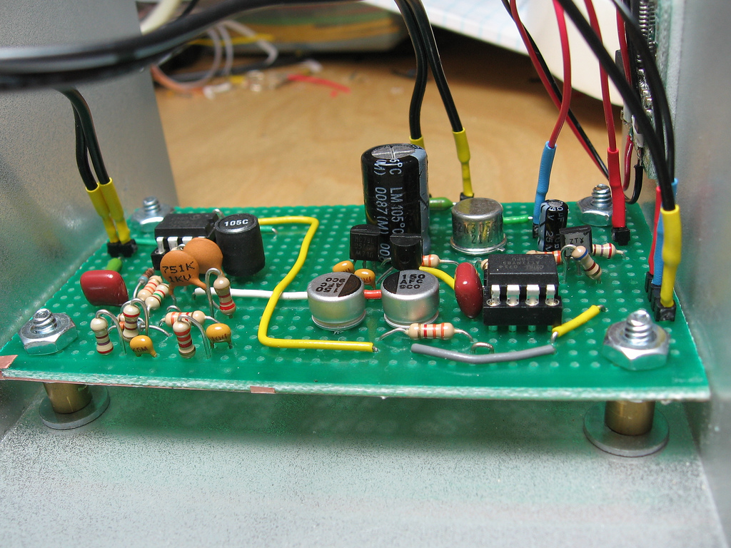
Self-contained TED receiver

My previous entry introduced a homebrew receiver for the powerline-based data protocol used by The Energy Detective. I just designed a second revision of that receiver. This one is self-contained: It gets power and modulated data from a 9V AC wall-wart transformer, and decoded data leaves via an RS-232 serial port at 9600 baud. Best of all the circuit is very simple: Just an 8-pin microcontroller and a single op-amp.

Major changes in this version:

  • DC power for the circuit is now provided by the 9V AC input, instead of a separate power supply. Previously this would have caused unacceptable levels of harmonic distortion in the input signal. In the new design, this is mitigated by an inductor (which forms an LC low-pass filter), and by the lower power consumption of a single modern op-amp versus three ancient op-amps.
  • By using a simpler filter design and a modern op-amp with a gain-bandwidth product of at least 10 MHz, the bandpass filter and amplifier can be built using only a single op-amp.

Note that the MAX475 op-amp I’m using has been discontinued by the manufacturer, and it’s now hard to find. I just used it because I had one handy in my junk drawer. I’ll verify this design with other op-amps as soon as I can, but it should work with just about any op-amp which can operate on a single-ended 5V supply, and which has a high enough GBW.

Firmware and schematics (PNG and EAGLE formats) are in Subversion and more info on the theory of operation was presented in my previous blog entry.

Interfacing with The Energy Detective

I recently bought The Energy Detective (TED), a pretty inexpensive and friendly way to keep tabs on your whole house’s electricity usage. It’s a lot like having a more featureful version of your utility company’s power meter, sitting on your kitchen counter. It can estimate your utility bill, and tell you how much electricity and money you’re using in real-time. The resolution is pretty good- 10 watts, 1 second.

As a product, I’ve been pretty happy with it. It does what it claims to, and the measurements seem to be fast and accurate. Of course, being the crazy hacker I am, I wanted to interface TED with other things. I don’t have a home automation system as such, but I did want to get real-time graphs of my electricity usage over various time periods. I also wanted the possibility to use TED as an information feed for various other display devices around the house. (But that’s a topic for another blog post…)

The stock TED package consists of two pieces: A measurement/transmit unit (MTU) and receive/display unit (RDU). The MTU has a pair of current transformers, and it installs entirely in your house’s breaker panel. It takes the power readings every second, and transmits them over the power lines to the RDU, which is just a little LCD panel that plugs into the wall. The RDU has a USB port, which you can use with TED’s “Footprints” software.

So, hoping that the USB port would do what I want, I bought the Footprints software for $45. The TED system itself is, in my opinion, a really good value. The Footprints software is not. As a consumer, I was disappointed by two main things:First of all- the UI lacks any polish whatsoever. It looks like a bad web page from the 90’s. Second of all, the data collection is not done in hardware, it’s implemented by a Windows service. This means you can’t collect data to graph unless you have a Windows PC running. Not exactly a power-efficient way to get detailed power usage graphs.

As a hobbyist, a few more things frustrated me about Footprints. The implementation was pretty amateurish. Their Windows service runs a minimal HTTP server which serves up data from an sqlite database in XML. The front end is actually just a Flash applet masquerading as a full application. Energy Inc, the company behind TED, has an API for Footprints: but you have to sign a legal agreement to get access to it, and I wasn’t able to get any details on what the API does and doesn’t include without signing the agreement. So, I opted not to. It would be much more fun to do a little reverse engineering…

So, I did. The end result is that I now have two ways of getting data out of my TED system.

Using the USB port

The TED RDU’s USB port is actually just a common FTDI usb-to-serial adapter. The RDU sends a binary packet every second, which includes all of the data accessible from the Footprints UI. This includes current power usage, current AC line voltage, utility rates, month-to-date totals, and anything else you’ve programmed into your RDU.

There has been some prior work on reverse engineering this protocol. The Misterhouse open source home automation project has a Perl module which can decode the TED messages.

Unfortunately, the Perl module in Misterhouse won’t work with more recent versions of the RDU like mine. The recent RDUs have a different packet length, and they require a polling command to be sent before they’ll reply with any data.

I found the correct polling command by snooping on Footprints’ serial traffic with Portmon. I also noticed a packet framing/escaping scheme, which explains some of the length variations that would have broken the module in Misterhouse.

The result is a Python module for receiving data from a TED RDU. It isn’t terribly featureful, but it should be pretty robust.

Direct from the wall socket

Now for the more exciting method: What about reading data directly from the power line, without using the TED receive/display unit at all? This could provide some exciting opportunities to embed a small and cheap TED receiver inside of other devices, and it would provide some insight on what exactly is being transmitted by the box in my breaker panel.

The TED RDU is pretty simple internally: A Dallas real-time clock, PIC18 microcontroller, chip-on-glass LCD, some buttons, and the TDA5051A, a single-chip home automation modem from Philips. This chip can receive and transmit ASK modulated signals at 1200 baud, with a carrier frequency of around 132 kHz.

Digi-key carries the TDA5051A, but I figured it would be more educational (and more hobbyist-friendly) to try and build a simpler receiver from scratch using only commonly available parts. The result is the following design, with an 8-pin AVR microcontroller and three op-amps:

Update: There is now a Revision 2 of the schematic, which uses only a single power supply and one op-amp.

  1. The power line is sampled via a 9V AC wall wart. With this design, it needs to be a separate isolated power supply. So far, I haven’t had any luck with using this same transformer to power the circuit. Any rectifier introduces high-frequency harmonics which drastically degrade the signal-to-noise ratio.
  2. The first stage is a 10x amplifier and 138kHz band-pass filter. This is from Texas Instrument’s “Filter Design in Thirty Seconds” cheat-sheet.
  3. The next stage is an amplifier and high-pass filter, to remove the last remnants of 60 Hz ripple.
  4. The third stage is just for amplification. In a design which used higher quality op-amps, this stage may not be necessary.
  5. After the third op-amp, the signal passes through an RC network which AC couples it, filters out high frequency noise which could cause glitches in the microcontroller’s I/O pin, and limits the current into the micro’s clamping diodes.
  6. At this point, we have an amplified digital signal which is still ASK-modulated:

The rest of the work happens in software. The ATtiny85 keeps itself quite busy:

  1. The AVR first applies a narrow digital band-pass filter, to strip out any ringing or other noise that remains after the analog band-pass filter.
  2. Next, a digital low-pass filter. This passes the 1200 baud serial data, but rejects higher frequency glitches.
  3. A threshold is applied, with hysteresis, to convert this data into a stream of ones and zeros.
  4. Next is a relatively typical software serial decoder, with majority-detect. The ASK modulated data has 8 data bits, 1 start bit, and 2 stop bits. Polarity is slightly different than typical RS-232. “1” is the presence of an ASK pulse, “0” is the absence of a pulse. Start bits are “1”, stop bits are both “0”.
  5. Using this serial engine, we receive an 11-byte packet.
  6. The packet is converted from TED’s raw format into a more human-readable (but still machine-friendly) serial format.
  7. The reformatted data is finally output via a software serial port at 9600 baud.

The end result, as viewed from a PC connected to the serial output pin:

HC=245 KW=001.324 V=121.138 CNT=023
HC=245 KW=001.335 V=121.135 CNT=024
HC=245 KW=001.348 V=121.072 CNT=025
HC=245 KW=001.345 V=121.021 CNT=026
HC=245 KW=001.345 V=121.044 CNT=027
HC=245 KW=001.324 V=121.152 CNT=028
HC=245 KW=001.314 V=121.280 CNT=029
HC=245 KW=001.314 V=121.306 CNT=030
HC=245 KW=001.311 V=121.297 CNT=031
HC=245 KW=001.349 V=121.232 CNT=032
HC=245 KW=001.347 V=121.228 CNT=033

The “KW” and “V” columns are self-explanatory. “HC” is my TED’s house code, and “CNT” is a packet counter. Normally in increments by one. If it skips any numbers, we missed a packet.

But wait, what’s wrong with this picture? The power and voltage readings have too much precision. The standard TED display unit will give you a resolution of 10 watts for power, and 0.1 volt. As my data above shows, the TED measurement unit is actually collecting data with far more precision. I can only guess why TED doesn’t give users more precision normally. I suspect they removed it because the extra precision may imply extra accuracy that may not exist.

So, what is TED actually sending? Once a second, it broadcasts an 11-byte packet over your power lines at 1200 baud:

  • Byte 0: Header (always 0x55)
  • Byte 1: House code
  • Byte 2: Packet counter
  • Byte 3: Raw power, bits 7-0
  • Byte 4: Raw power, bits 15-8
  • Byte 5: Raw power, bits 23-16
  • Byte 6: Raw voltage, bits 7-0
  • Byte 7: Raw voltage, bits 15-8
  • Byte 8: Raw voltage, bits 23-16
  • Byte 9: Unknown (Flags?)
  • Byte 10: Checksum

Pretty straightforward. I don’t know the actual A/D converter precision in the measurement/transmit unit, but both the power and voltage readings are sent on the wire as 24-bit raw numbers. I’m still not sure what byte 9 is. In my measurements, it hovered around 250, sometimes jumping up or down by one. It may be some kind of flag byte, or maybe it measures power line frequency? The checksum is dead simple: Add every byte in the packet (modulo 256), and the checksum byte ensures the result is zero.

To figure out what to do with these raw measurements, I collected data simultaneously with my circuit and with the TED RDU’s USB interface. Both sets of results went into a spreadsheet. After removing outliers, I did a linear regression. The resulting linear function is what you’ll find in the current firmware for my homebrew receiver. The following plots from the spreadsheet are a pretty striking illustration of the additional precision available via my raw interface:

The top graph shows power line voltage as recorded by the TED RDU. The second graph shows the raw values I’m receiving from the TED MTU. The bottom graph shows the correlation between the two, in blue, and my linear regression, in red.

I plan to keep improving the circuit. Hopefully there’s a way to get both data and power from a single supply, without dealing with any annoying high-voltage circuitry. If there is any interest, I might make a kit available. If you’re interested, post a comment and let me know what features you’d like. USB port? Serial port? Display?

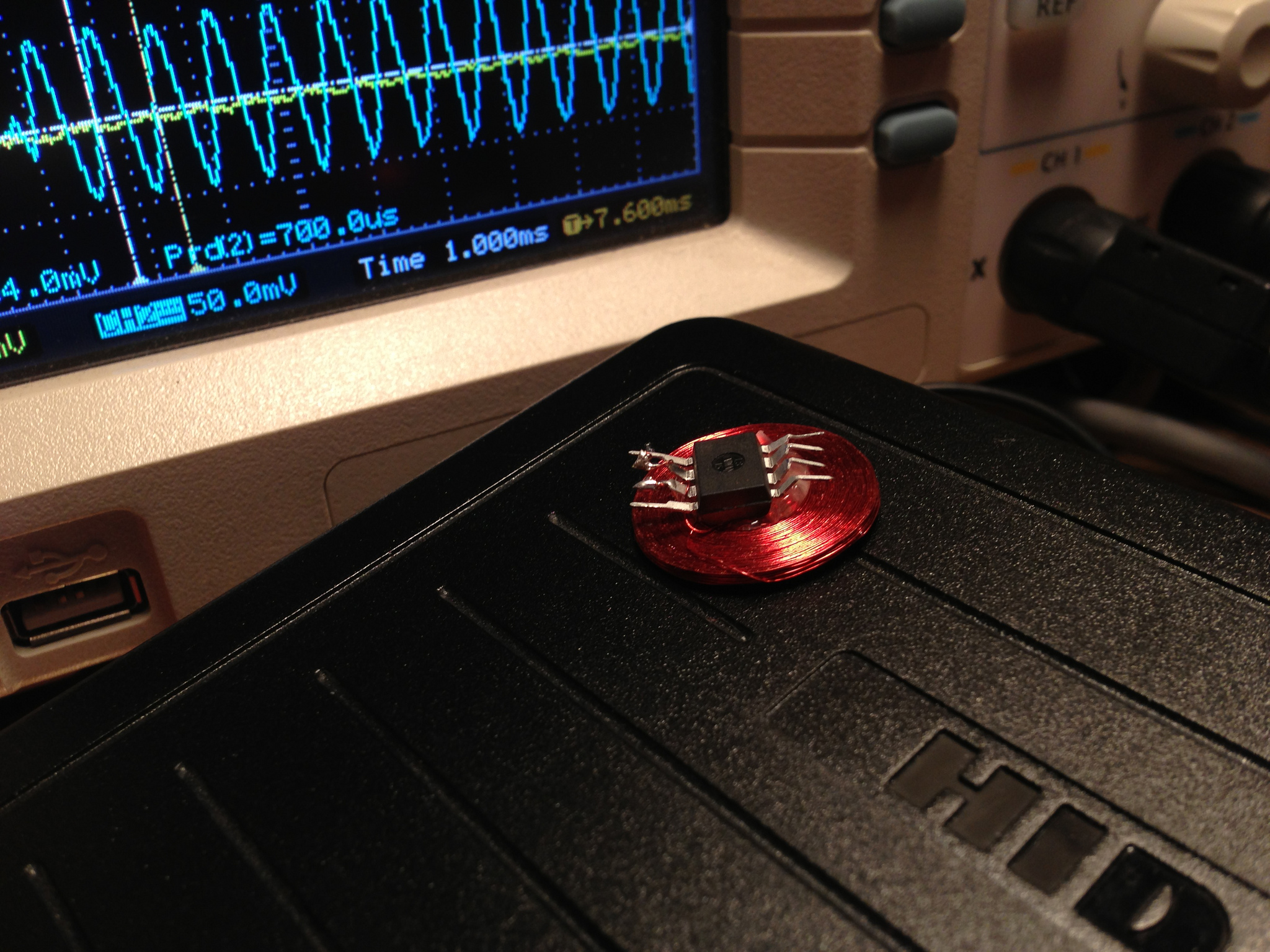
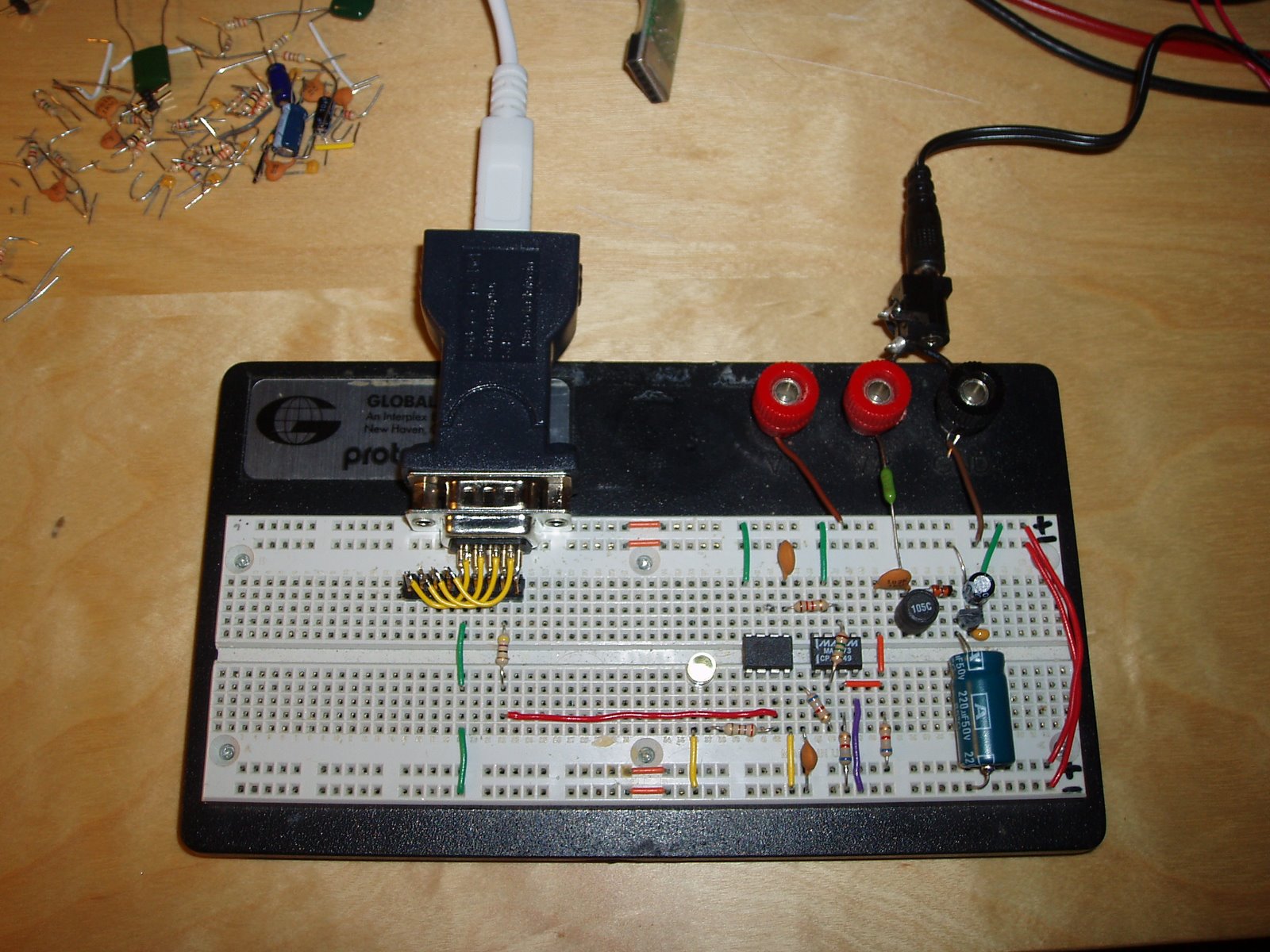
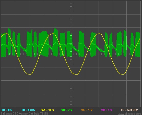
Using an AVR as an RFID tag

Experiments in RFID, continued…

Last time, I posted an ultra-simple “from scratch” RFID reader, which uses no application-specific components: just a Propeller microcontroller and a few passive components. This time, I tried the opposite: building an RFID tag using no application-specific parts.

Well, my solution is full of dirty tricks, but the results aren’t half bad. I used an Atmel AVR microcontroller (the ATtiny85) and a coil. That’s it. You can optionally add a couple of capacitors to improve performance with some types of coils, but with this method it’s possible to build a working RFID tag just by soldering a small inductor to an AVR chip:

image

image

The above prototype emulates an EM4102-style tag- a very popular style of low-frequency RFID tag which stores a 40-bit unique ID. I can read my bogus ID value (0x12345678AB) using Parallax’s RFID reader. Below is another prototype, with a larger coil and a couple of capacitors for added range and stability. It is programmed to emulate a HID prox card, a simple FSK-modulated tag with a 44-bit payload. I can read this card successfully with my garage door opener. This one is a little large to conveniently carry around, but a smaller AVR package should help.

image

AVRFID Tag Prototype

So, the shiny electrical tape is beautiful, but how does this thing even work? The power pins on the microcontroller aren’t even connected!

As I said, this makes use of several dirty tricks:

  • The coil actually powers the AVR through two of its I/O pins. Nearly every chip out there has clamping diodes on its I/O pins, which prevent voltages on that pin from rising above the chip’s supply voltage or sinking below ground. These diodes are useful for arresting static discharge.When you first hold the RFID tag up to a reader, the chip has no power- the supply voltage is zero. When the coil starts to pick up power from the RFID reader, these two I/O pins are presented with a sine wave, a few volts in amplitude. Anywhere that sine wave exceeds the supply voltage, some energy is diverted from the coil to the chip’s supply rails, via the clamping diode. The end result is that the chip is powered, and the coil’s sine wave is truncated. The top and bottom of the sine have been chopped off, and it looks a lot more like a square wave now.
  • Power filtering using the AVR’s die capacitance. In the smaller prototype, there is no power filtering capacitor at all. In fact, the power is filtered by the internal capacitance of the power planes in the AVR’s silicon die. This isn’t much, but it makes the power supply stable enough that we can execute code even though the supply is pulsing at 125 kHz.
  • Very low voltage operation. This particular ATtiny85 chip is specified for operation at voltages as low as 2.5v. The extended voltage range version (I didn’t have any of these handy) is specified down to 1.8v. But I’m running these AVRs at barely over 1 volt. At these voltages, the normal AVR clock oscillators don’t work- but I can get away with this because of the next hack…
  • The coil is the AVR’s clock source. The inductor isn’t just hooked up to any I/O pin: it’s actually connected to the AVR’s clock input. Remember the square-ish wave we’re left with after the clamping diodes suck away some power? That waveform is now our clock input. The microcontroller is executing code at 125 kHz, in lockstep with the RFID reader’s carrier wave.
  • Firmware? What firmware? At such low speeds, the chip’s firmware looks less like a program, and more like a sequence of I/O operations to perform in sync with each carrier clock cycle. There aren’t a lot of cycles to spare. In the EM4102 protocol, you could potentially do some useful work with the 32 clock cycles you have between each bit. With the HID protocol, though, you need to output an FSK edge as often as once every 4 clock cycles. As a result, the firmware on the RFID tag is extremely dumb. The “source code” is really just a set of fancy assembler macros which convert an RFID tag code into a long sequence of I/O instructions.

The fact that this thing works at all is quite a testament to the robust design of the AVR. The latest AVRFID source is in Subversion, as usual.

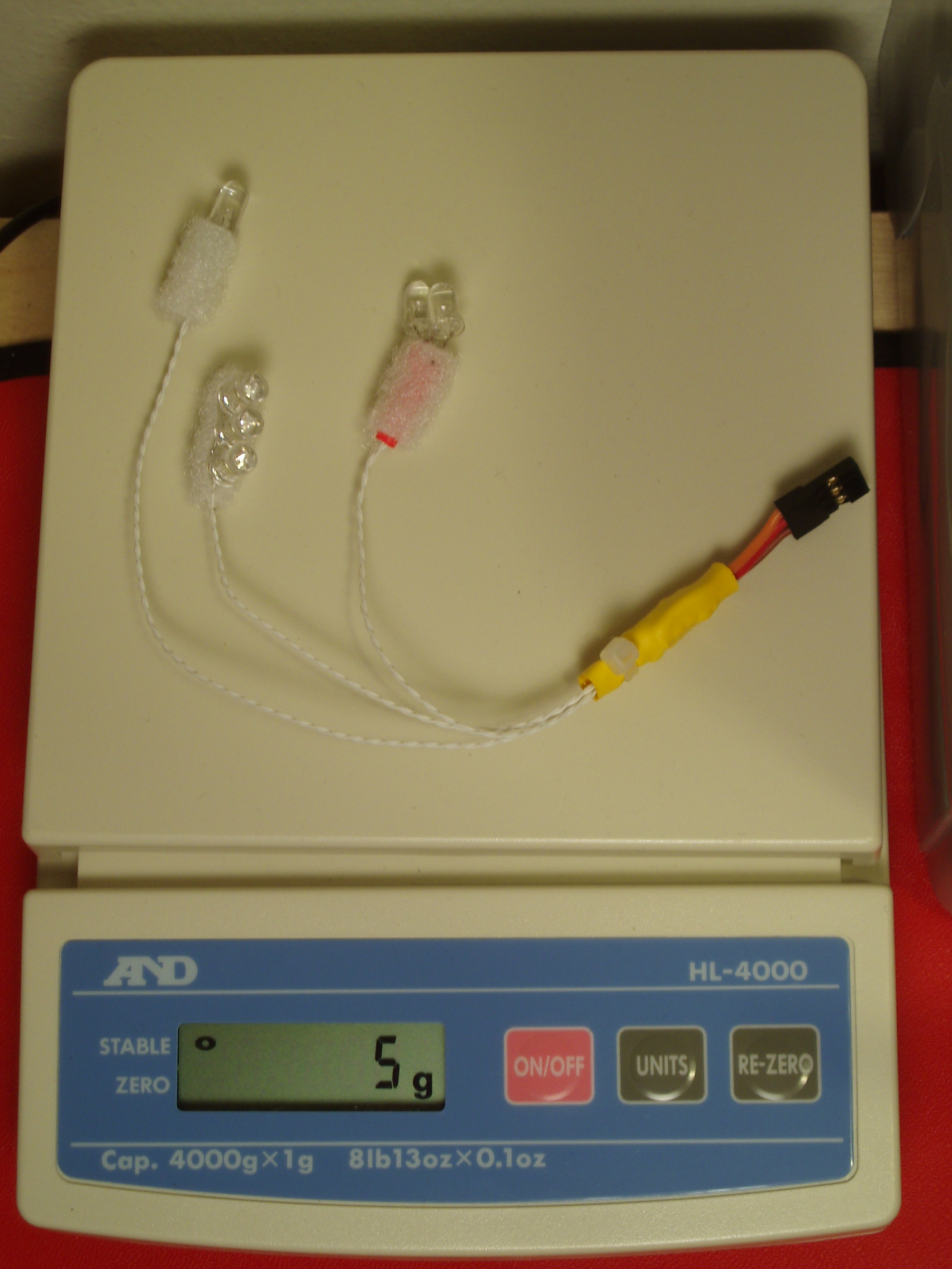
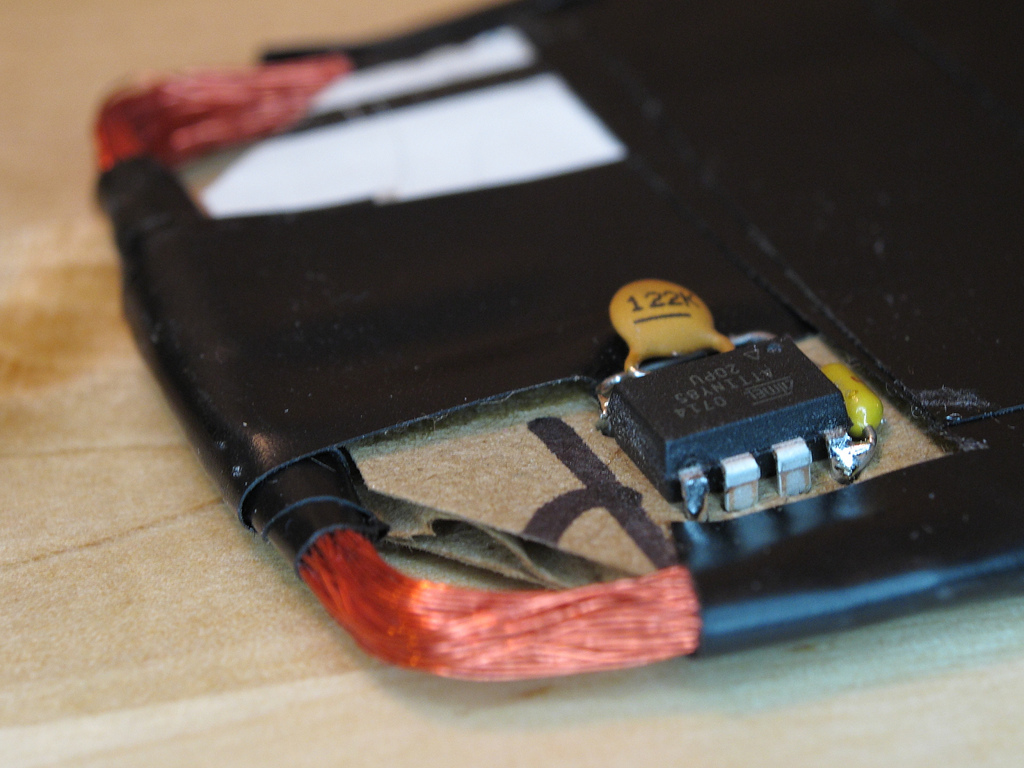
R/C helicopter lights, Revision A.5

Atmel is going to personally revoke my electrical engineering license if they ever find out what’s in that yellow heat-shrink blob, but I now have a shiny new 5 gram version of my helicopter light kit =D

This version has all the same remote-control dimming and strobe capabilities of the heavier Revision A. The only practical drawback is that it isn’t quite as bright.

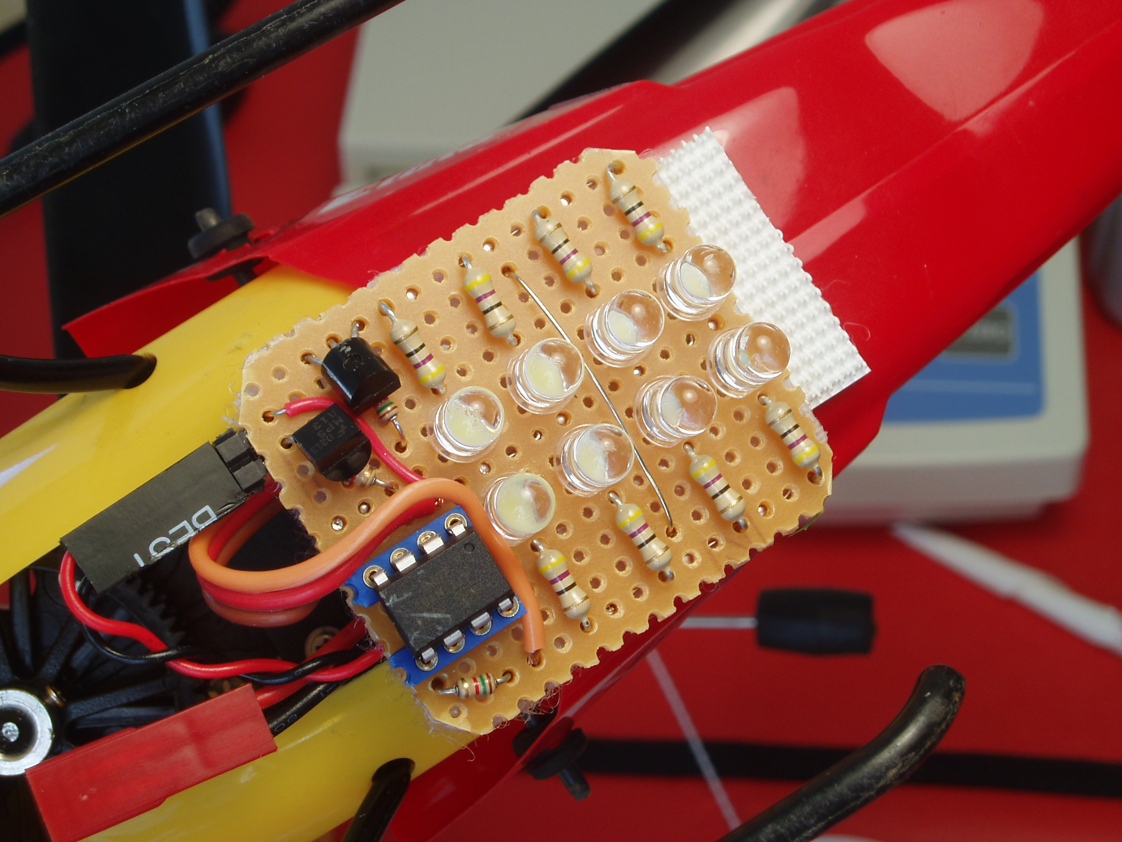
Hardware sketch: R/C helicopter light kit

As great as it is to finish a professional-looking hardware project with optimum component choices and full design documentation, I love the feeling of sketching in hardware (or as I’ve called it in the past, improvisational electrical engineering). Despite all the faults and rough edges in today’s development tools, we do live in a world now where it’s easy turn an idea into a working prototype with very little time and money.

Flying in the dark

Yesterday’s hardware sketch was a light system for my helicopter, an E-Flite Blade CX2. I wanted:

  • A way to fly at night. Real navigation lights would be nice, but for starters I just want the whole helicopter body to glow.
  • A way to take off and land safely. I’ve flown with only a body light before, and it’s really hard to land when you don’t know quite where the ground is.
  • A bright strobe, for extra visibility and attention.
  • A way to control the lights remotely, using the extra servo channel on the Blade CX2’s radio.

My finished prototype takes the form of a small circuit board that attaches under the canopy with velcro. That board holds the light control electronics, plus a bright white searchlight. It connects to the radio (for power and control) and to the internally-mounted body lights. The body lights are just bare LEDs attached to the inside of the tail and canopy with velcro. One white LED in the tail, one red and one yellow LED in the canopy.

Both sets of lights have full brightness control using a single knob on the BCX2’s transmitter. At the knob’s minimum setting, all lights are off. As you turn it up, first the body lights fade on. Next, the searchlight fades on. Just before hitting the maximum setting, all the lights are on at full brightness. If you turn the knob farther, to its maximum, the searchlight goes into strobe mode.

There are some rough edges, but it works remarkably well for such a simple design. The total weight is about 15 grams. It’s heavier than I’d like, but it doesn’t effect flight performance much. I’d still like some orientation lights mounted on the skids or the sides of the control PCB, but the body light is pretty easy to fly by. The searchlight is incredibly visible at maximum brightness. Even from an altitude of 50 feet or so, the light casts a bright spot on the ground.

Technical details

Skip this section unless you’re a huge dork 😉

The light controller uses an Atmel ATtiny85 microcontroller (kind of overkill) and a pair of NPN Darlington transistors to drive the LEDs. The microcontroller’s firmware is quite simple. An assembly-language loop times the pulses coming in from the radio, then the firmware decides on a corresponding lighting mode and sets up the AVR’s hardware PWM peripheral accordingly.

This hardware sketch was built with whatever parts I had handy. The LEDs are low-tech by today’s standards, the microcontroller was kind of overkill, and MOSFETs would have been better than the Darlington transistors. If I were building a second revision of this, I’d make a few improvements:

  • All surface-mount parts and a PCB, to decrease size and weight.
  • Use a single 1-watt Luxeon LED instead of an array of cheapo white LEDs.
  • To drive the Luxeon LED, I’ll probably want a simple buck converter.
  • Logarithmic LED brightness control, rather than linear.
  • Side-emitting navigation lights, mounted directly on the main PCB.
  • Optimize the firmware for low-power operation when the lights are off. Right now it costs about 8mA to run the AVR in its pulse-detecting loop at 8 MHz.
  • Start mass-producing and selling these 😉 It’s much better than any commercial light kit I’ve seen for the Blade CX2, and the parts are quite cheap.