Using an AVR as an RFID tag

Experiments in RFID, continued…

Last time, I posted an ultra-simple “from scratch” RFID reader, which uses no application-specific components: just a Propeller microcontroller and a few passive components. This time, I tried the opposite: building an RFID tag using no application-specific parts.

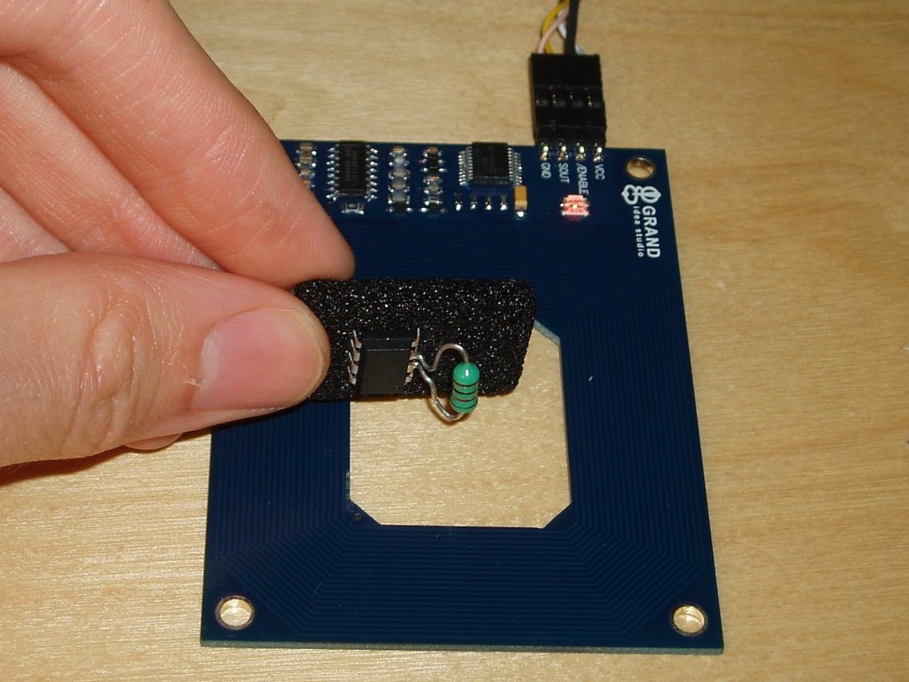
Well, my solution is full of dirty tricks, but the results aren’t half bad. I used an Atmel AVR microcontroller (the ATtiny85) and a coil. That’s it. You can optionally add a couple of capacitors to improve performance with some types of coils, but with this method it’s possible to build a working RFID tag just by soldering a small inductor to an AVR chip:

image

image

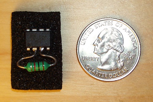
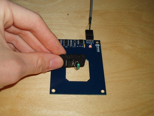
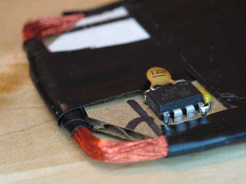
The above prototype emulates an EM4102-style tag- a very popular style of low-frequency RFID tag which stores a 40-bit unique ID. I can read my bogus ID value (0x12345678AB) using Parallax’s RFID reader. Below is another prototype, with a larger coil and a couple of capacitors for added range and stability. It is programmed to emulate a HID prox card, a simple FSK-modulated tag with a 44-bit payload. I can read this card successfully with my garage door opener. This one is a little large to conveniently carry around, but a smaller AVR package should help.

image

AVRFID Tag Prototype

So, the shiny electrical tape is beautiful, but how does this thing even work? The power pins on the microcontroller aren’t even connected!

As I said, this makes use of several dirty tricks:

  • The coil actually powers the AVR through two of its I/O pins. Nearly every chip out there has clamping diodes on its I/O pins, which prevent voltages on that pin from rising above the chip’s supply voltage or sinking below ground. These diodes are useful for arresting static discharge.When you first hold the RFID tag up to a reader, the chip has no power- the supply voltage is zero. When the coil starts to pick up power from the RFID reader, these two I/O pins are presented with a sine wave, a few volts in amplitude. Anywhere that sine wave exceeds the supply voltage, some energy is diverted from the coil to the chip’s supply rails, via the clamping diode. The end result is that the chip is powered, and the coil’s sine wave is truncated. The top and bottom of the sine have been chopped off, and it looks a lot more like a square wave now.
  • Power filtering using the AVR’s die capacitance. In the smaller prototype, there is no power filtering capacitor at all. In fact, the power is filtered by the internal capacitance of the power planes in the AVR’s silicon die. This isn’t much, but it makes the power supply stable enough that we can execute code even though the supply is pulsing at 125 kHz.
  • Very low voltage operation. This particular ATtiny85 chip is specified for operation at voltages as low as 2.5v. The extended voltage range version (I didn’t have any of these handy) is specified down to 1.8v. But I’m running these AVRs at barely over 1 volt. At these voltages, the normal AVR clock oscillators don’t work- but I can get away with this because of the next hack…
  • The coil is the AVR’s clock source. The inductor isn’t just hooked up to any I/O pin: it’s actually connected to the AVR’s clock input. Remember the square-ish wave we’re left with after the clamping diodes suck away some power? That waveform is now our clock input. The microcontroller is executing code at 125 kHz, in lockstep with the RFID reader’s carrier wave.
  • Firmware? What firmware? At such low speeds, the chip’s firmware looks less like a program, and more like a sequence of I/O operations to perform in sync with each carrier clock cycle. There aren’t a lot of cycles to spare. In the EM4102 protocol, you could potentially do some useful work with the 32 clock cycles you have between each bit. With the HID protocol, though, you need to output an FSK edge as often as once every 4 clock cycles. As a result, the firmware on the RFID tag is extremely dumb. The “source code” is really just a set of fancy assembler macros which convert an RFID tag code into a long sequence of I/O instructions.

The fact that this thing works at all is quite a testament to the robust design of the AVR. The latest AVRFID source is in Subversion, as usual.

Comments
70 Responses to “Using an AVR as an RFID tag”
  1. blueskies says:

    what programmer do i need to program the aTtiny85?

    • Beth says:

      Pretty much any AVR programmer should work. The internet should have lots of designs for ICSP serial programmers. I use an AVR Dragon nowadays, but when I built these tags I was using an old JTAG parallel port cable.

      You might check out avrdude, the open source AVR programmer software, and look at the list of supported hardware. That’ll give you a good idea for what’s out there.

      Good luck!

  2. Sam says:

    Wonder if a TI MSP430 would be a better bet than an AVR for this?

  3. Anonymous says:

    Hi. This project is really cool. When constructing the coil, you solder the ends of the coil to pins 5 and 6 right?

    • garyamort says:

      No, that’s the trick. You don’t solder the coil to anything but itself. The coil converts the broadcast RF signal to a small amount of AC power for any circuit within the coil’s area of affect. The resistor creates a “circuit” by connecting 2 of the pins on the chip, so an incredibly small bit of ac power is now flowing through the circuit[the sine wave]. The chip has built in current protection for it’s digital “input/output” pins – this protection basically cuts the top and bottom of the sinewave off and sends it into the internal power circuit – thus powering the device.

      This converts the sinewave into a squarish wave which has a set frequency[the frequency of the RF signal] – or in other words – a clock. So since he picked the external clock pin as one of his 2 pins – it also provides an external clock to the chip.

      You don’t need a schematic, all you need to do is connect the resistor between any GPIO pin and the CLCK pin. That’s it, circuit complete.

      I’m not sure what the capicitor[?] is used for in the circuit – smoothing out the power so it is steady? From his initial post, it will run without it, so I’m assuming,

  4. Grant says:

    A schematic would be useful…

  5. Stewie says:

    Blown my mid. How the f**k. Understanding this is one thing, but coming up with it to begin with!? Amazing.

    • MWP says:

      Agreed with Stewie.
      It may be a “oh, of course that works” thing after youve read about it…. but coming up with that in the first place is genius.

  6. Los says:

    Ok, so I want make this a 35 bit system rather than a 26. I have come across some problems.
    1) when I change the amount of bits to 35, I run out of flash so I get an error lol
    simple fix, get a diff uC with more flash.
    2) I got the card to send 35 bits by arbitrarily changing HID_MFG_CODE to 0×01600 ( im not sure
    what this actually does, if someone wants to explain that would be awesome! :) )
    3) i need to change the amount of bits for HID_SITE_CODE to be at least an 11 bit number and
    finally change the HID_UNIQUE_ID to be at least a 19 bit number.
    the problem i get is when i change the UNIQUE_ID and SITE_CODE to bits other than the set 16 and 8,
    it just no longer works.
    any help would be appreciated greatly!
    Thanks so much for this post by the way! Great work!

  7. marcelo says:

    Hi,
    Is it possible to have the hex file for this? I would like to test the concept but i do not use “c”.

    Thanks,
    marcelo

  8. This is so awesome. A little schematic would be very much appreciated. Thank you.

  9. Janek says:

    Hi, if the author can post schematic and parts list?

  10. n3mesys says:

    Hi Beth,

    I will thank you so much for this nice tutorial!

    My question is if it is possible with a ATMega88 or something else ???

    Sorry for my baaad English.

    Have a nice day,

  11. Peter says:

    I gues it supports UID rewriting? Any experiences with a proxmark3 or an original HID reader?

  12. Will says:

    Does inductance value of the coil matter? I’m looking at 125khz RFID with an attiny85 and a 180uH inductor…

  13. Amazing!!! Every single dirty-hack is impressive by itself, and you’ve used 5 of them to get this RFID tag working!

Trackbacks
Check out what others are saying...
  1. [...] a lo-freq emulator, like this one and a lo-freq reader with this chip from Melexis; my fellow [...]


Leave A Comment