I recently bought The Energy Detective (TED), a pretty inexpensive and friendly way to keep tabs on your whole house’s electricity usage. It’s a lot like having a more featureful version of your utility company’s power meter, sitting on your kitchen counter. It can estimate your utility bill, and tell you how much electricity and money you’re using in real-time. The resolution is pretty good- 10 watts, 1 second.
As a product, I’ve been pretty happy with it. It does what it claims to, and the measurements seem to be fast and accurate. Of course, being the crazy hacker I am, I wanted to interface TED with other things. I don’t have a home automation system as such, but I did want to get real-time graphs of my electricity usage over various time periods. I also wanted the possibility to use TED as an information feed for various other display devices around the house. (But that’s a topic for another blog post…)
The stock TED package consists of two pieces: A measurement/transmit unit (MTU) and receive/display unit (RDU). The MTU has a pair of current transformers, and it installs entirely in your house’s breaker panel. It takes the power readings every second, and transmits them over the power lines to the RDU, which is just a little LCD panel that plugs into the wall. The RDU has a USB port, which you can use with TED’s “Footprints” software.
So, hoping that the USB port would do what I want, I bought the Footprints software for $45. The TED system itself is, in my opinion, a really good value. The Footprints software is not. As a consumer, I was disappointed by two main things:First of all- the UI lacks any polish whatsoever. It looks like a bad web page from the 90’s. Second of all, the data collection is not done in hardware, it’s implemented by a Windows service. This means you can’t collect data to graph unless you have a Windows PC running. Not exactly a power-efficient way to get detailed power usage graphs.
As a hobbyist, a few more things frustrated me about Footprints. The implementation was pretty amateurish. Their Windows service runs a minimal HTTP server which serves up data from an sqlite database in XML. The front end is actually just a Flash applet masquerading as a full application. Energy Inc, the company behind TED, has an API for Footprints: but you have to sign a legal agreement to get access to it, and I wasn’t able to get any details on what the API does and doesn’t include without signing the agreement. So, I opted not to. It would be much more fun to do a little reverse engineering…
So, I did. The end result is that I now have two ways of getting data out of my TED system.
Using the USB port
The TED RDU’s USB port is actually just a common FTDI usb-to-serial adapter. The RDU sends a binary packet every second, which includes all of the data accessible from the Footprints UI. This includes current power usage, current AC line voltage, utility rates, month-to-date totals, and anything else you’ve programmed into your RDU.
There has been some prior work on reverse engineering this protocol. The Misterhouse open source home automation project has a Perl module which can decode the TED messages.
Unfortunately, the Perl module in Misterhouse won’t work with more recent versions of the RDU like mine. The recent RDUs have a different packet length, and they require a polling command to be sent before they’ll reply with any data.
I found the correct polling command by snooping on Footprints’ serial traffic with Portmon. I also noticed a packet framing/escaping scheme, which explains some of the length variations that would have broken the module in Misterhouse.
The result is a Python module for receiving data from a TED RDU. It isn’t terribly featureful, but it should be pretty robust.
- Get the latest TED Python Module (navi-misc/python/ted.py) from my Subversion repository.
Direct from the wall socket
Now for the more exciting method: What about reading data directly from the power line, without using the TED receive/display unit at all? This could provide some exciting opportunities to embed a small and cheap TED receiver inside of other devices, and it would provide some insight on what exactly is being transmitted by the box in my breaker panel.
The TED RDU is pretty simple internally: A Dallas real-time clock, PIC18 microcontroller, chip-on-glass LCD, some buttons, and the TDA5051A, a single-chip home automation modem from Philips. This chip can receive and transmit ASK modulated signals at 1200 baud, with a carrier frequency of around 132 kHz.
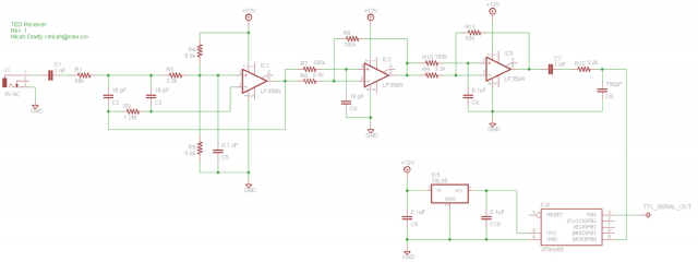
Digi-key carries the TDA5051A, but I figured it would be more educational (and more hobbyist-friendly) to try and build a simpler receiver from scratch using only commonly available parts. The result is the following design, with an 8-pin AVR microcontroller and three op-amps:
Update: There is now a Revision 2 of the schematic, which uses only a single power supply and one op-amp.
- The power line is sampled via a 9V AC wall wart. With this design, it needs to be a separate isolated power supply. So far, I haven’t had any luck with using this same transformer to power the circuit. Any rectifier introduces high-frequency harmonics which drastically degrade the signal-to-noise ratio.
- The first stage is a 10x amplifier and 138kHz band-pass filter. This is from Texas Instrument’s “Filter Design in Thirty Seconds” cheat-sheet.
- The next stage is an amplifier and high-pass filter, to remove the last remnants of 60 Hz ripple.
- The third stage is just for amplification. In a design which used higher quality op-amps, this stage may not be necessary.
- After the third op-amp, the signal passes through an RC network which AC couples it, filters out high frequency noise which could cause glitches in the microcontroller’s I/O pin, and limits the current into the micro’s clamping diodes.
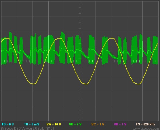
- At this point, we have an amplified digital signal which is still ASK-modulated:
The rest of the work happens in software. The ATtiny85 keeps itself quite busy:
- The AVR first applies a narrow digital band-pass filter, to strip out any ringing or other noise that remains after the analog band-pass filter.
- Next, a digital low-pass filter. This passes the 1200 baud serial data, but rejects higher frequency glitches.
- A threshold is applied, with hysteresis, to convert this data into a stream of ones and zeros.
- Next is a relatively typical software serial decoder, with majority-detect. The ASK modulated data has 8 data bits, 1 start bit, and 2 stop bits. Polarity is slightly different than typical RS-232. “1” is the presence of an ASK pulse, “0” is the absence of a pulse. Start bits are “1”, stop bits are both “0”.
- Using this serial engine, we receive an 11-byte packet.
- The packet is converted from TED’s raw format into a more human-readable (but still machine-friendly) serial format.
- The reformatted data is finally output via a software serial port at 9600 baud.
The end result, as viewed from a PC connected to the serial output pin:
HC=245 KW=001.324 V=121.138 CNT=023
HC=245 KW=001.335 V=121.135 CNT=024
HC=245 KW=001.348 V=121.072 CNT=025
HC=245 KW=001.345 V=121.021 CNT=026
HC=245 KW=001.345 V=121.044 CNT=027
HC=245 KW=001.324 V=121.152 CNT=028
HC=245 KW=001.314 V=121.280 CNT=029
HC=245 KW=001.314 V=121.306 CNT=030
HC=245 KW=001.311 V=121.297 CNT=031
HC=245 KW=001.349 V=121.232 CNT=032
HC=245 KW=001.347 V=121.228 CNT=033
The “KW” and “V” columns are self-explanatory. “HC” is my TED’s house code, and “CNT” is a packet counter. Normally in increments by one. If it skips any numbers, we missed a packet.
But wait, what’s wrong with this picture? The power and voltage readings have too much precision. The standard TED display unit will give you a resolution of 10 watts for power, and 0.1 volt. As my data above shows, the TED measurement unit is actually collecting data with far more precision. I can only guess why TED doesn’t give users more precision normally. I suspect they removed it because the extra precision may imply extra accuracy that may not exist.
So, what is TED actually sending? Once a second, it broadcasts an 11-byte packet over your power lines at 1200 baud:
- Byte 0: Header (always 0x55)
- Byte 1: House code
- Byte 2: Packet counter
- Byte 3: Raw power, bits 7-0
- Byte 4: Raw power, bits 15-8
- Byte 5: Raw power, bits 23-16
- Byte 6: Raw voltage, bits 7-0
- Byte 7: Raw voltage, bits 15-8
- Byte 8: Raw voltage, bits 23-16
- Byte 9: Unknown (Flags?)
- Byte 10: Checksum
Pretty straightforward. I don’t know the actual A/D converter precision in the measurement/transmit unit, but both the power and voltage readings are sent on the wire as 24-bit raw numbers. I’m still not sure what byte 9 is. In my measurements, it hovered around 250, sometimes jumping up or down by one. It may be some kind of flag byte, or maybe it measures power line frequency? The checksum is dead simple: Add every byte in the packet (modulo 256), and the checksum byte ensures the result is zero.
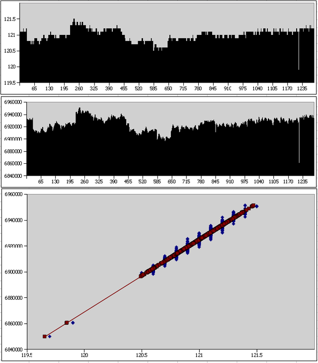
To figure out what to do with these raw measurements, I collected data simultaneously with my circuit and with the TED RDU’s USB interface. Both sets of results went into a spreadsheet. After removing outliers, I did a linear regression. The resulting linear function is what you’ll find in the current firmware for my homebrew receiver. The following plots from the spreadsheet are a pretty striking illustration of the additional precision available via my raw interface:
The top graph shows power line voltage as recorded by the TED RDU. The second graph shows the raw values I’m receiving from the TED MTU. The bottom graph shows the correlation between the two, in blue, and my linear regression, in red.
I plan to keep improving the circuit. Hopefully there’s a way to get both data and power from a single supply, without dealing with any annoying high-voltage circuitry. If there is any interest, I might make a kit available. If you’re interested, post a comment and let me know what features you’d like. USB port? Serial port? Display?
- You can get the latest schematics and firmware from my Subversion repository.


