I should have blogged about this long ago, as I’ve been working on it off and on for about three months now, but today I reached an arbitrary milestone that compels me to post 😉 I’m still actively working on this project, so I’ll try to make updates occasionally, and if I end up putting together an actual project web page I’ll link it from here.
My latest tinkery hardware and embedded systems project is a homebrew laser scanner. You know, the kind you see at planetariums- sweep a laser beam around on the wall really fast, and draw vector graphics. Commercial laser scanners have been around for decades now, but buying a complete system is still really pricy, even on eBay. Besides, where’s the fun in that?
There are plenty of examples of homebrew laser scanners on the internet. Many people have wired up a pair of loudspeakers, hard disk actuators, or other readily available mechanisms to an amplifier and used them for simple laser graphics. This will make some pretty wiggly patterns on the wall, but it isn’t a real vector graphics display. The best example I know of for a totally built-from-scratch laser projector (not using commercial galvo actuators) actually uses custom hand-wound galvanometers. Very nice.
So, this has been done before, but I still find it an interesting project. This is actually my third attempt at a laser scanner. My first one I built when I was in my early teens, when solid state lasers were first starting to become “affordable”. I pointed my shiny new $40 laser diode module, dimmer than today’s $5 laser pointer, at a few spinning mirrors on cheap DC motors. Instant laser spirograph, with basic speed control over the parallel port of my 8086 PC.
About 4 years ago, in college, I made my second attempt. This one used a cheap red laser pointer, fragments of scrap mirrors, and a couple of old hard disks hot glued together. The mechanical parts were shoddy, but the electronics were worse. It had an extremely low-power open loop amplifier, and it couldn’t draw much more than circles.
This being my third try, I figured I had to get it right. I still stuck to my original goals:
- Only readily available off-the-shelf mechanical and electronic parts.
- Simple hardware, powerful software.
- Performant enough to display low- or medium-complexity vector graphics.
- Portable.
And, this was the result:

To differentiate it from all the other hobby laser projectors out there, it has a pretty nice set of features:
- Compact and portable.
- All digital. In the whole project, no board-level analog signals are present.
- Based around the Parallax Propeller multi-core microcontroller.
- Optical position sensors, for closed-loop servo feedback.
- High-power 30mW green laser, with software-adjustable brightness level.
- Bluetooth interface. The only external wire is power.
- Vector graphics virtual machine. To efficiently send graphics data over the relatively slow Bluetooth link, frames can be encoded using a simple instruction set which lets the projector itself perform line and curve interpolation.
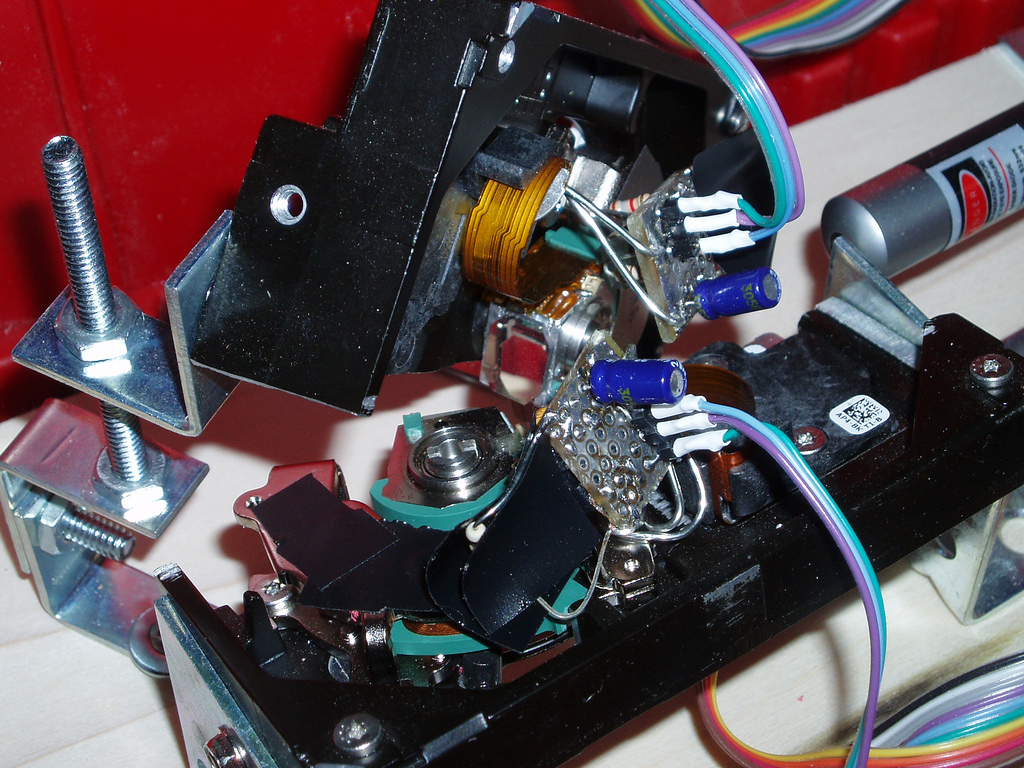
The internals:


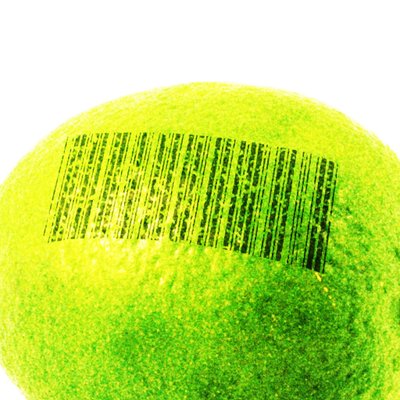
- Two hard disk voice coil motors (VCMs) with front-silvered mirrors.
- Position sensors: Each consists of two LEDs (one stationary, one moving) and a TSL230R light-to-frequency converter chip.
- Temperature sensors: Dallas DS18B20 1-wire sensors, mounted on the magnet bracket for each VCM.
- Laser module: A dangerously bright 30mW green laser from DealExtreme.
- Control electronics: A Propeller prototype board with two LMD18200 H-bridges to drive the VCMs, a Darlington transistor to drive the laser, Bluetooth module from Spark Fun, and a few resistors and capacitors. That’s all.
So, the hardware is really simple. Building this projector involved a lot of cutting, gluing, and soldering- but building a second one could probably be done in a weekend. The complexity is in the software, and especially the firmware. The on-board microcontroller is responsible for reading and filtering the light sensor data, updating the servo loop for each VCM at 40 KHz and generating pulse-width modulation at several MHz, reading the temperature sensors, generating laser brightness control PWM at up to 80 MHz, decoding the vector graphics instruction stream, communicating over the Bluetooth link, and supervising the whole operation so we don’t melt a VCM coil or shear any end-stops in half- all simultaneously. The Propeller, luckily, has 8 symmetric processing cores. This project keeps all of them busy.
I’m just barely at the point where I can start conducting meaningful testing that shows me the projector’s true limits. The hardware and firmware are feature-complete, but the desktop software does little more than provide a pretty wxPython UI for high-level control and calibration. So far I’ve been testing it with simple hand-drawn shapes, which the control software can resample for constant laser velocity.
Today I wrote an importer for the ILDA Image Transfer Format, and tried running the industry-standard ILDA Test Pattern. The pattern is designed for a speed of 12K (12000 points per second), but modern commercial laser scanners can typically run it at 30K or higher.

Well, it looks like my projector currently maxes out at about ILDA 4K. Compared to a modern commercial scanner, this sucks, but it’s not bad for a couple of hard disks. I’ll have to try tweaking my servo loop some more (or cranking up the VCMs from 12 volts to 24, maybe with liquid cooling 😉 to see if I can go any faster, but this is certainly enough precision and speed to draw words, shapes, and hopefully some simple animated characters. (Kirby, Yoshi, maybe a spinning Parallax Propeller beanie…)
I’ll keep working on the software, and posting new photos as I make progress. The latest firmware (written in Spin and Assembly) and client software (in Python) are available in Subversion (navi-misc/laserprop), with an MIT-style license.