
I don’t normally write bloggy posts on every version of every source file I check in, but every so often an older project sees some more activity, and I love the opportunity to revisit software I wrote years ago. Sometimes I wonder why I wrote such-and-such thing that way and oh my god what an ugly hack. But usually it’s just refreshing to think about a problem I haven’t thought about in a while.
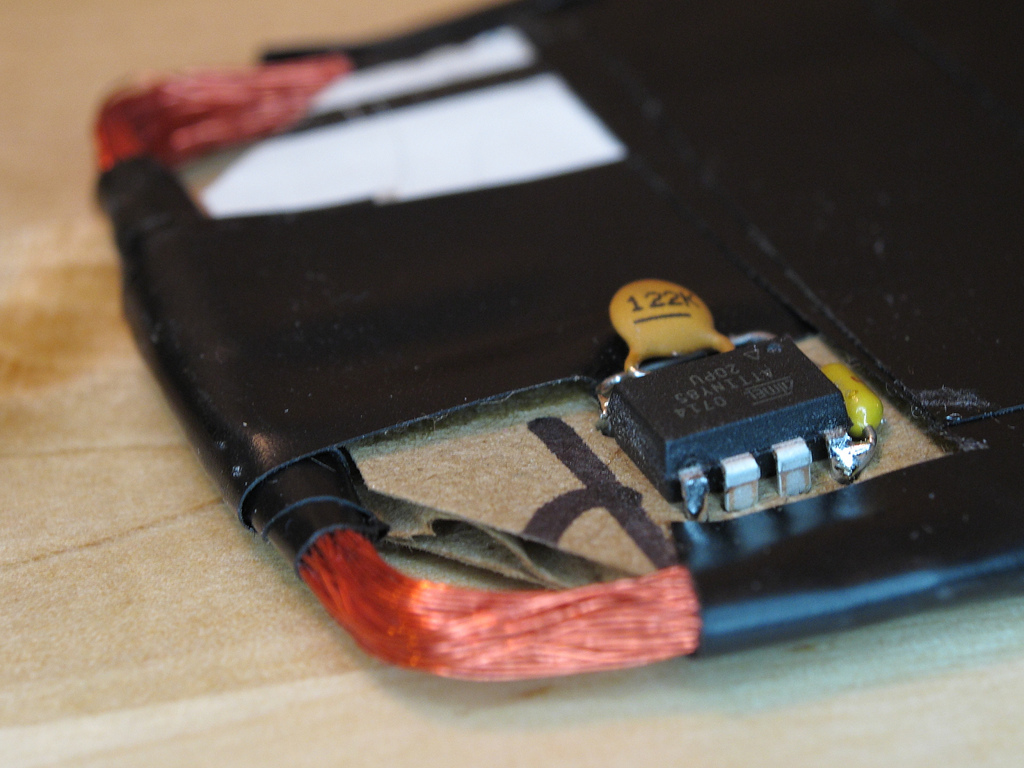
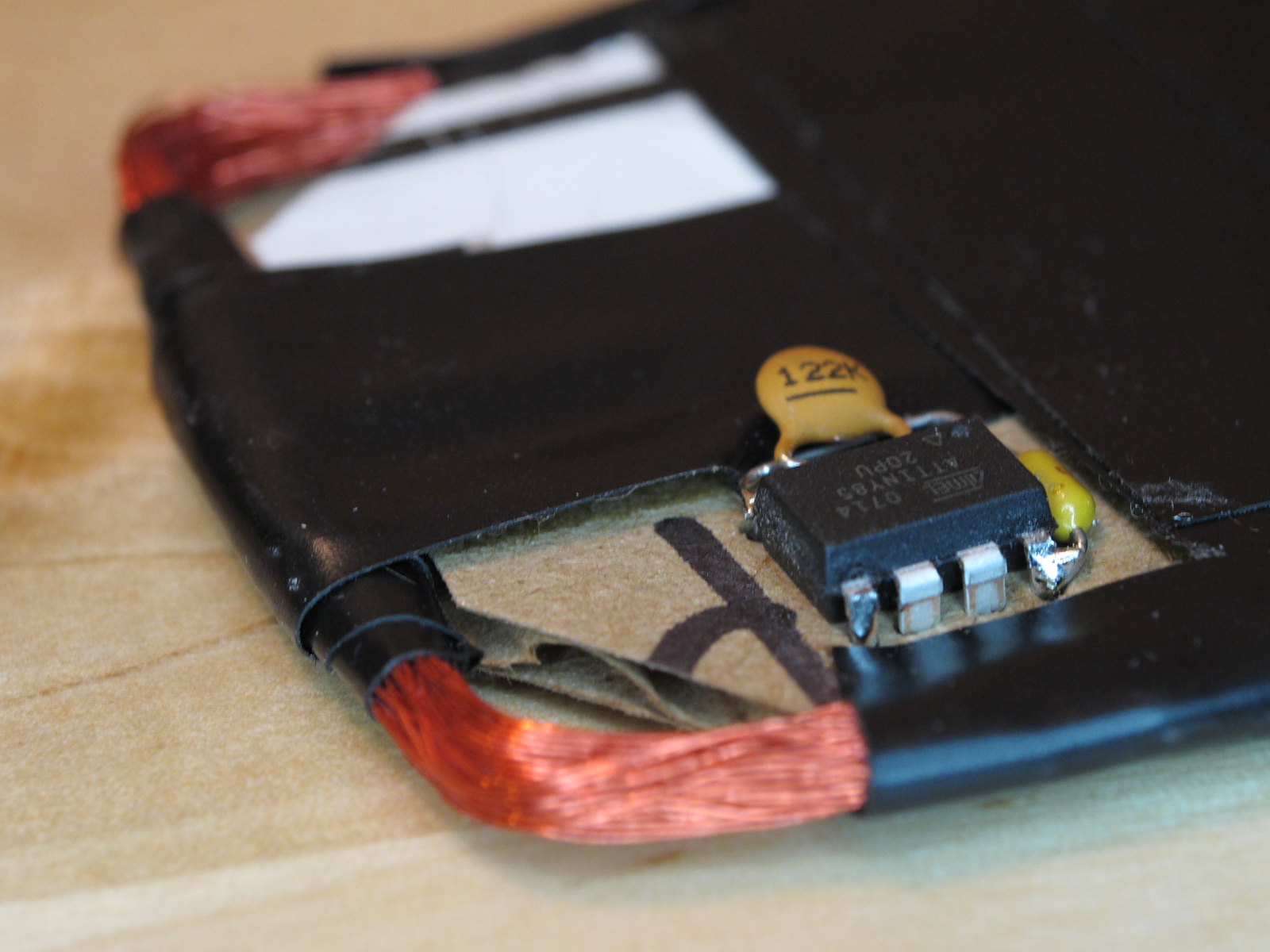
The AVRFID was a quick but rather unique project, back from when I was on a bit of a 125 kHz RFID binge culminating in the design, construction, and installation of a proxcard reader for my garage door. While I was fidgeting around with such things, it occurred to me that you could (using a whole host of dirty tricks) convince a general-purpose 8-bit microcontroller like the AVR to function as a passive RFID tag.
Since then, I received a couple patches:
- Luke Koops improved the FSK modulation for HID tags, so that the resulting waveform is much more regular.
- Cesar Fernandez described the HID card format in more detail, and implemented a parity calculation. The 45-bit code is actually composed of four distinct fields:
- A 20-bit manufacturer code or header, constant for all HID cards.
- An 8-bit site code, unique to the particular security installation.
- A 16-bit unique ID. These are often printed in decimal on the back of the card, and they seem roughly sequential.
- An odd parity bit, covering the other 44 bits.
I didn’t have my RFID gear handy, so Cesar was kind enough to verify it with his official HID reader. So I stamped a new version number on it. If you’re interested in building your own HID card emulator, there is now a much better chance it will actually work with your reader :)
- Grab the latest source code (navi-misc/avrfid/avrfid.S) from Subversion.
/*
 * Software-only implementation of a passive low-frequency RFID tag,
 * using an AVR microcontroller.
 *
 * Version 1.1, 2010-06-15
 *
 * Copyright (c) 2008-2010 Micah Dowty <micah@navi.cx>
 * See end of file for license terms. (BSD style)
 * Improved HID modulation contributed by Luke Koops <luke.koops@gmail.com>
 * HID parity bit support contributed by Cesar Fernandez <cex123@gmail.com>
 *
 * Supports EM4102-style tags, and the HID 125 kHz prox card protocol.
 * The card format and ID number are set below, with #defines.
 *
 * Basic schematic:
 *
 *              ATtiny85
 *              +--------------+
 *            --| RST      Vcc |--
 *    +- L1 ----| B3/CLKI  SCK |--
 *    +---------| B4      MISO |--
 *            --| GND     MOSI |--
 *              +--------------+
 *
 * L1 is about 1 mH. It and the AVR are the only components.
 * All other pins should be unconnected.
 *
 * AVR notes:
 *
 *   - Low-voltage parts are better, but I've had success using
 *     this with the non-extended voltage range parts as well.
 *
 *   - Program the fuses for an external clock with no divider.
 *     On the ATtiny85, this means setting lfuse to 0xC0.
 *     Note that after you set this fuse, your programmer will
 *     need to supply a clock on pin 2 for subsequent programming
 *     operations.
 *
 * Optional parts:
 *
 *   - Power decoupling capacitor, between 0.1 and 10uF.
 *     Bigger is generally better, as it will increase the
 *     usable range- but if you use this tag with readers that
 *     have a pulsed carrier wave, bigger caps may take too long
 *     to charge.
 *
 *   - A load capacitor, in parallel with L1. This will depend
 *     on your coil. For physically small coils, the internal
 *     capacitance of the AVR seems to be enough. For larger coils,
 *     it may be necessary to use a cap here. Experiment to find the
 *     best value.
 *
 *   - A header, for in-circuit programming. You'll need to expose nearly
 *     every pin on the chip, since the AVR will also need an external
 *     clock.
 *
 *   - If you want to make an active (powered) tag, you could hook a 3V
 *     battery up to the Vcc and GND pins on the AVR. To decrease the power
 *     usage when idle, you may want to hook a large (a couple megohm)
 *     pull-down resistor to the clock input, to be sure CLKI doesn't float
 *     when there is no RF field present.
 *
 * Theory of operation:
 *
 *   Like all passive RFID tags, this circuit is powered by the 125 kHz
 *   carrier wave emitted by the RFID reader. In our case, the coil is
 *   just connected to two AVR I/O pins. We're actually powering the AVR
 *   through its protective clamping diodes, and the power is retained by
 *   the AVR die's internal capacitance.
 *
 *   This is a very weak power source, and the AVR typically gets little
 *   over a volt of Vcc. As a result, most of the AVR's oscillators won't
 *   start. We can, however, use the carrier wave itself as a clock as well.
 *   This also makes the software easy, since the instruction clock is also
 *   the RF clock. We're already clamping the coil voltage into something
 *   resembles a square wave, so this makes a good external clock source.
 *
 *   To send data back to the reader, passive RFID tags can selectively
 *   attenuate the reader's carrier wave. Most RFID tags do that with a
 *   transistor which shorts their coil. We accomplish this by driving the
 *   coil I/O pins to ground, by toggling the DDRB register. Since the I/O
 *   drivers on the AVR are weaker than the RF signal, we still get enough
 *   of a pulse to provide the CLKI input.
 *
 *   And that's about all there is to it. The software is quite simple- we
 *   are mostly just using assembler macros to convert the desired RFID tag
 *   code into sequences of subroutine calls which output bits. We can't
 *   get too fancy with the software, since it's only executing at 125 kHz.
 *
 */

/************ Configuration *****************************************/

// Uncomment exactly one format:

#define FORMAT_IS_EM4102
//#define FORMAT_IS_HID

// For the EM4102: An 8-bit manufacturer ID and 32-bit unique ID.

#define EM4102_MFR_ID		0x12
#define EM4102_UNIQUE_ID	0x3456789A

/*
 * For the HID card:
 *   A 20-bit manufacturer code, 8-bit site code, and 16-bit unique ID, 1-bit odd parity.
 *
 * Manufacturer code is fixed. If modified, HID readers do not recognise the tag.
 * (This may also be a kind of fixed header.) Tested on HID readers with 26-bit wiegand output.
 */

#define HID_MFG_CODE        0x01002  // Do not modify
#define HID_SITE_CODE       0x9F
#define HID_UNIQUE_ID       1326     // May be written on the back of the card

/************ Common ************************************************/

#ifndef __ASSEMBLER__
#define __ASSEMBLER__
#endif
#include <avr/io.h>

.global main

#define OUT_PINS       _BV(PINB3) | _BV(PINB4)

    .macro	delay cycles
    .if \cycles > 1
    rjmp	.+0
    delay	(\cycles - 2)
    .elseif \cycles > 0
    nop
    delay	(\cycles - 1)
    .endif
    .endm

    .macro	manchester bit, count=1
    .if		\count
    manchester (\bit >> 1), (\count - 1)
    .if		\bit & 1
    baseband_1
    baseband_0
    .else
    baseband_0
    baseband_1
    .endif
    .endif
    .endm

    .macro	stop_bit
    baseband_0
    baseband_1_last
    .endm


/************ EM4102 Implementation *********************************/

/*
 * The common EM4102 cards use Manchester encoding, at a fixed rate of
 * 64 RF clocks per bit. This means 32 clock cycles per half-bit (baseband
 * code). There are a total of 64 manchester-encoded bits per packet. 40
 * of these are payload, 9 bits are header (all ones) and one bit is a stop
 * bit (zero). All other bits are parity, with one row parity bit every
 * 4 bits, and four column parity bits at the end of the packet.
 */

#ifdef FORMAT_IS_EM4102

#define ROW_PARITY(n)  ( (((n) & 0xF) << 1) | \
                         (((n) ^ ((n) >> 1) ^ ((n) >> 2) ^ ((n) >> 3)) & 1) )

#define COLUMN_PARITY  ( (EM4102_MFR_ID >> 4) ^        \
                         (EM4102_MFR_ID) ^             \
                         (EM4102_UNIQUE_ID >> 28) ^    \
                         (EM4102_UNIQUE_ID >> 24) ^    \
                         (EM4102_UNIQUE_ID >> 20) ^    \
                         (EM4102_UNIQUE_ID >> 16) ^    \
                         (EM4102_UNIQUE_ID >> 12) ^    \
                         (EM4102_UNIQUE_ID >> 8) ^     \
                         (EM4102_UNIQUE_ID >> 4) ^     \
                         (EM4102_UNIQUE_ID) )

main:

        .macro	baseband_0
        rcall	baseband30_0
        rjmp	.+0
        .endm

        .macro	baseband_1
        rcall	baseband30_1
        rjmp	.+0
        .endm

        .macro	baseband_1_last
        rcall	baseband30_1
        rjmp	main
        .endm

        .macro	header
        manchester 0x1FF, 9
        .endm

        header
        manchester	ROW_PARITY(EM4102_MFR_ID >> 4), 5
        manchester	ROW_PARITY(EM4102_MFR_ID >> 0), 5
        manchester	ROW_PARITY(EM4102_UNIQUE_ID >> 28), 5
        manchester	ROW_PARITY(EM4102_UNIQUE_ID >> 24), 5
        manchester	ROW_PARITY(EM4102_UNIQUE_ID >> 20), 5
        manchester	ROW_PARITY(EM4102_UNIQUE_ID >> 16), 5
        manchester	ROW_PARITY(EM4102_UNIQUE_ID >> 12), 5
        manchester	ROW_PARITY(EM4102_UNIQUE_ID >> 8), 5
        manchester	ROW_PARITY(EM4102_UNIQUE_ID >> 4), 5
        manchester	ROW_PARITY(EM4102_UNIQUE_ID >> 0), 5
        manchester	COLUMN_PARITY, 4
        stop_bit

        /*
         * Emit a 0 at the baseband layer.
         * Takes a total of 30 clock cycles, including call overhead.
         */
baseband30_0:
        ldi	r16, OUT_PINS		// 1
        rjmp	baseband30		// 2

        /*
         * Emit a 1 at the baseband layer.
         * Takes a total of 30 clock cycles, including call overhead.
         */
baseband30_1:
        ldi	r16, 0			// 1
        rjmp	baseband30		// 2

        /*
         * Internal routine for baseband32_0 and _1. Must use
         * a total of 24 clock cycles. (32 - 1 ldi - 2 rjmp - 3 rcall)
         */
baseband30:
        out	_SFR_IO_ADDR(DDRB), r16		// 1
        delay	19				// 19
        ret					// 4

#endif /* FORMAT_IS_EM4102 */


/************ HID Implementation *********************************/

/*
 * This works with the HID 125 kHz prox cards I've tested it with,
 * but there are undoubtedly other formats used by HID. My cards are
 * marked with the model number "HID 0004H".
 *
 * These cards use both manchester encoding and FSK modulation. The FSK
 * modulation represents zeroes and ones using 4 and 5 full RF cycles, respectively.
 * An entire baseband bit lasts 50 RF cycles.
 *
 * Each packet begins with a header consisting of the baseband bit pattern "000111".
 * After that, we have 45 manchester-encoded bits before the packet repeats. The
 * last bit appears to be a stop bit, always zero. The previous 20 bits encode the
 * 6-digit unique ID, which is printed on the back of the card. The other 24 bits
 * have an unknown use. They could be a site code or manufacturing code. In the cards
 * I've examined, these bits are constant.
 */

#ifdef FORMAT_IS_HID

#define ODD_PARITY(n)  ((( ((n) >> 0 ) ^ ((n) >> 1 ) ^ ((n) >> 2 ) ^ ((n) >> 3 ) ^ \
                           ((n) >> 4 ) ^ ((n) >> 5 ) ^ ((n) >> 6 ) ^ ((n) >> 7 ) ^ \
                           ((n) >> 8 ) ^ ((n) >> 9 ) ^ ((n) >> 10) ^ ((n) >> 11) ^ \
                           ((n) >> 12) ^ ((n) >> 13) ^ ((n) >> 14) ^ ((n) >> 15) ^ \
                           ((n) >> 16) ^ ((n) >> 17) ^ ((n) >> 18) ^ ((n) >> 19) ^ \
                           ((n) >> 20) ^ ((n) >> 21) ^ ((n) >> 22) ^ ((n) >> 23) ^ \
                           ((n) >> 24) ^ ((n) >> 25) ^ ((n) >> 26) ^ ((n) >> 27) ^ \
                           ((n) >> 28) ^ ((n) >> 29) ^ ((n) >> 30) ^ ((n) >> 31) ) & 1) ^ 1)
main:
        eor	r16, r16
        ldi	r17, OUT_PINS
loop:

        /*
         * Toggle the output modulation, in the specified number
         * of total clock cycles.
         */
        .macro toggle clocks
        delay	(\clocks - 2)
        eor	r16, r17
        out	_SFR_IO_ADDR(DDRB), r16
        .endm

        /*
         * Emit a 0 at the baseband layer. (Toggle every 4 cycles, for 50 cycles)
	 * There was an rjmp that got us to the beginning of the loop, so drop
	 * 2 cycles from the delay if this is the first bit.  That will give the
	 * appropriate delay before the toggle.
	 *
	 * From observing the HID card, each 0 bit is either 48 or 52 cycles.
	 * The length alternates to keep the average at 50.  This keeps the
	 * waveform smooth, and keeps each bit in its 50 cycle time slot.
	 *
         * We don't have time for a function call, so we just chew
         * up lots of flash...
         */
        .macro	baseband_0
	.if startloop
	toggle	2		// 4
	.equ startloop, 0
	.else
        toggle	4		// 4
	.endif
        toggle	4		// 8
        toggle	4		// 12
        toggle	4		// 16
        toggle	4		// 20
        toggle	4		// 24
        toggle	4		// 28
        toggle	4		// 32
        toggle	4		// 36
        toggle	4		// 40
        toggle	4		// 44
        toggle	4		// 48
	.if evenzero
	.equ evenzero, 0
	.else
	toggle	4		// 52
	.equ evenzero, 1
	.endif
        .endm

        /*
         * Emit a 1 at the baseband layer. (Toggle every 5 cycles, for 50 cycles)
         */
        .macro	baseband_1
	.if startloop
	toggle	3		// 4
	.equ startloop, 0
	.else
        toggle	5		// 4
	.endif
        toggle	5		// 10
        toggle	5		// 15
        toggle	5		// 20
        toggle	5		// 25
        toggle	5		// 30
        toggle	5		// 35
        toggle	5		// 40
        toggle	5		// 45
        toggle	5		// 50
        .endm

        .macro header
	.equ evenzero, 0
	.equ startloop, 1
        baseband_0
        baseband_0
        baseband_0
        baseband_1
        baseband_1
        baseband_1
        .endm


	/*
	 * This should add up to 45 bits.
	 *
	 * Some cards may use different 45-bit codes: For example,
	 * a Wiegand code, or something more site-specific. But the
	 * cards that I've seen use a 20-bit manufacturer code,
	 * 8-bit site code, 16-bit unique ID, and a single parity bit.
	 *
	 * If your card uses ad ifferent coding scheme, you can add,
	 * remove, and modify these 'manchester' macros. Just make sure
	 * the result adds up to the right number of bits.
	 */
        header
        manchester	HID_MFG_CODE, 20
	manchester	HID_SITE_CODE, 8
	manchester	HID_UNIQUE_ID, 16
	manchester	ODD_PARITY(HID_MFG_CODE ^ HID_SITE_CODE ^ HID_UNIQUE_ID), 1

        rjmp	loop


#endif /* FORMAT_IS_HID */

/*****************************************************************/

/*
 * Permission is hereby granted, free of charge, to any person
 * obtaining a copy of this software and associated documentation
 * files (the "Software"), to deal in the Software without
 * restriction, including without limitation the rights to use,
 * copy, modify, merge, publish, distribute, sublicense, and/or sell
 * copies of the Software, and to permit persons to whom the
 * Software is furnished to do so, subject to the following
 * conditions:
 *
 * The above copyright notice and this permission notice shall be
 * included in all copies or substantial portions of the Software.
 *
 * THE SOFTWARE IS PROVIDED "AS IS", WITHOUT WARRANTY OF ANY KIND,
 * EXPRESS OR IMPLIED, INCLUDING BUT NOT LIMITED TO THE WARRANTIES
 * OF MERCHANTABILITY, FITNESS FOR A PARTICULAR PURPOSE AND
 * NONINFRINGEMENT. IN NO EVENT SHALL THE AUTHORS OR COPYRIGHT
 * HOLDERS BE LIABLE FOR ANY CLAIM, DAMAGES OR OTHER LIABILITY,
 * WHETHER IN AN ACTION OF CONTRACT, TORT OR OTHERWISE, ARISING
 * FROM, OUT OF OR IN CONNECTION WITH THE SOFTWARE OR THE USE OR
 * OTHER DEALINGS IN THE SOFTWARE.
 */