
Tag: old-project
-
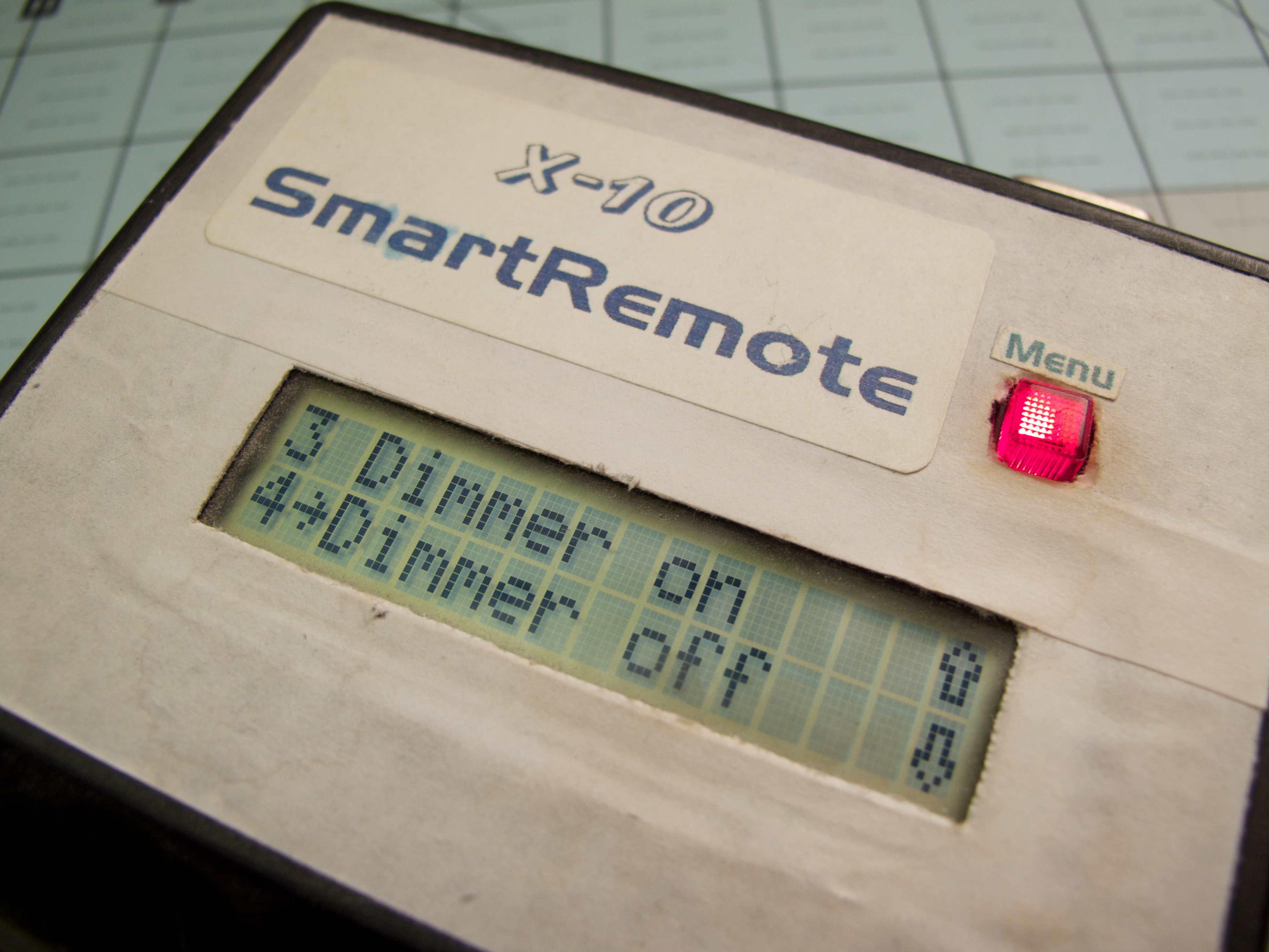
X-10 SmartRemote
I’m not even sure why I built this at all. I guess I did always have a childhood fascination with making things that seemed professional in some way. A simulacrum of some expensive piece of A/V equipment, or simple computer games that came in a shoe box with construction-paper cover art. This is another ancient…
-
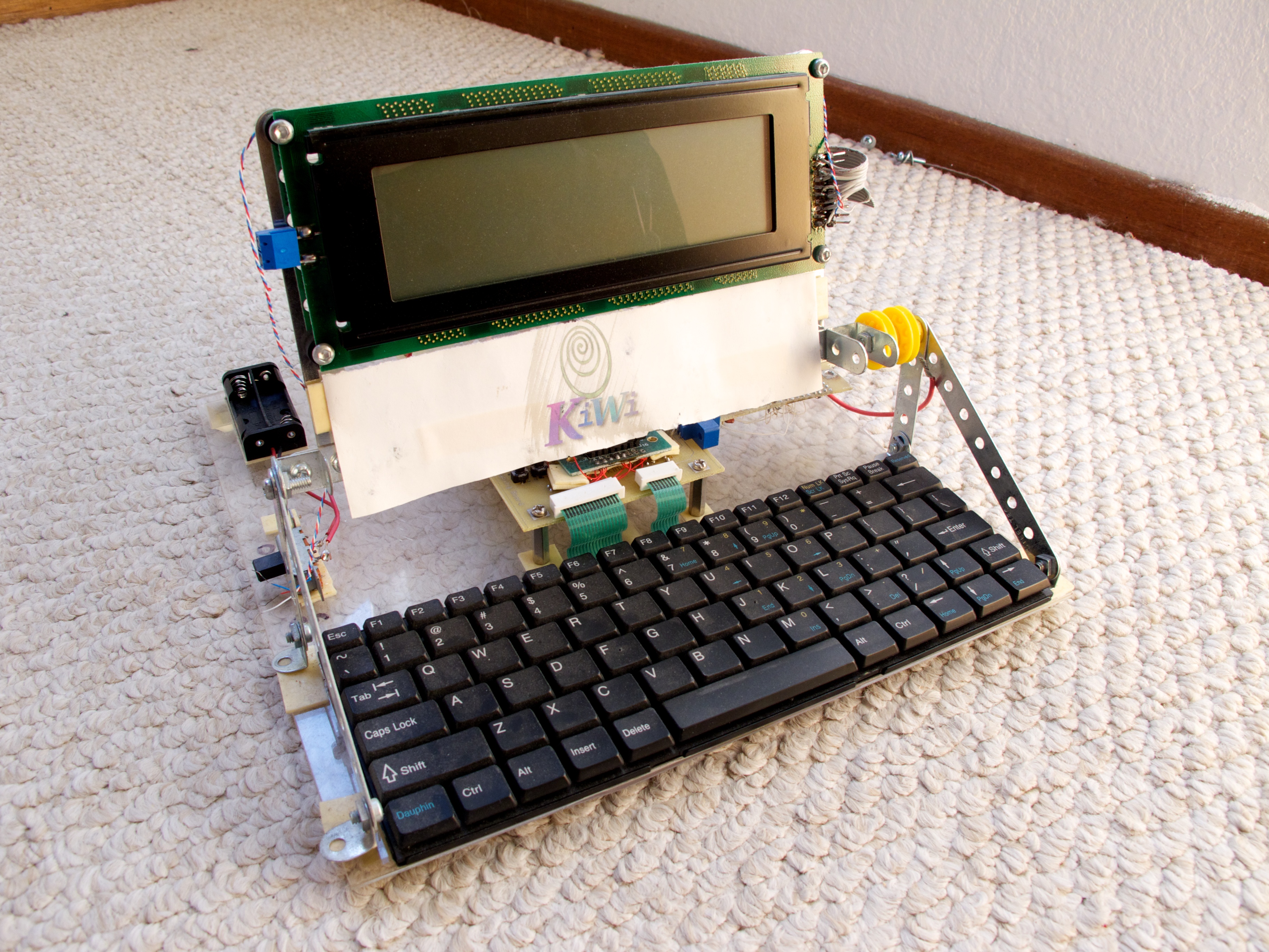
Kiwi
Another nostalgic post about an old project that I’m purging from my closet… This time from late-1999 through mid-2000. The Kiwi was a rather ambitious built-from-scratch Linux PDA that I spent my high school years on. My original goal for this project was reminiscent of the One Laptop Per Child project. I liked typing my…
-
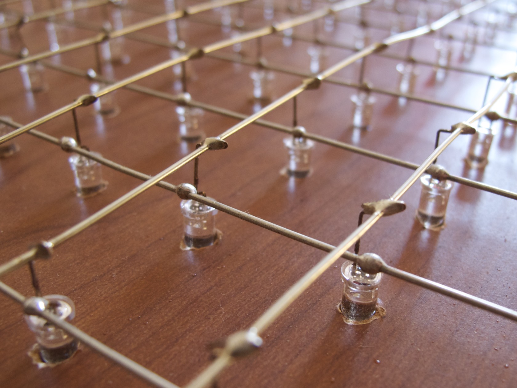
LEDboard/144
This is a 9×16 LED matrix I made by hand back in 2004, with LEDs I had left over from another, even sillier project. It has a USB interface powered by a PIC16C765 microcontroller, one of the first to feature a built-in USB device interface. This video post is something of a eulogy for the…
-
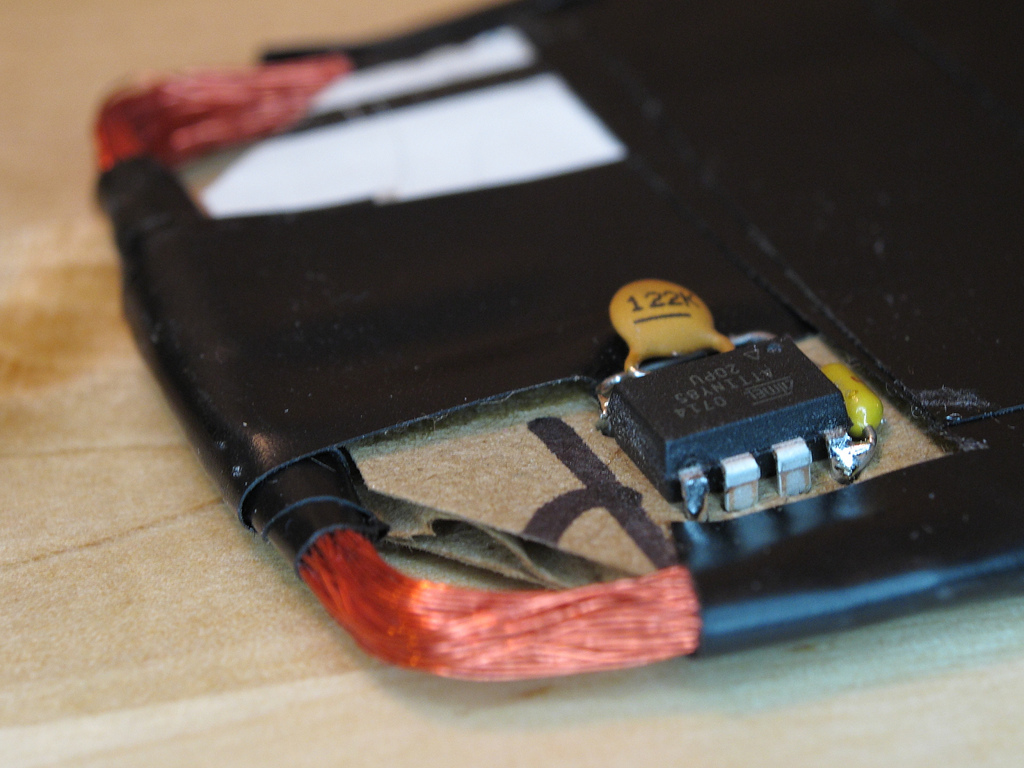
AVRFID 1.1 Firmware
I don’t normally write bloggy posts on every version of every source file I check in, but every so often an older project sees some more activity, and I love the opportunity to revisit software I wrote years ago. Sometimes I wonder why I wrote such-and-such thing that way and oh my god what an…