
Previously on the bloggy blog, I posted a few of my projects related to home data acquisition and to The Energy Detective (TED), a whole-house power measurement device. I made a set of homebrew wireless temperature sensors that display graphs on a digital picture frame, I reverse engineered the TED protocol, built a small self-contained open source TED receiver, and used that design to make a nifty clock.
So, I wanted to take the next step and set up real-time power usage graphing alongside the temperature graphs. The only problem: My sensor receivers are on a different power line phase than the TED. I’d need a TED receiver that can deal with all of the noise that switching power supplies put out, and receive weak TED signals that have been coupled across phases by the utility’s pole transformer. There were probably easier ways to solve this problem, but it was a good excuse to get more experience with analog electronics 🙂
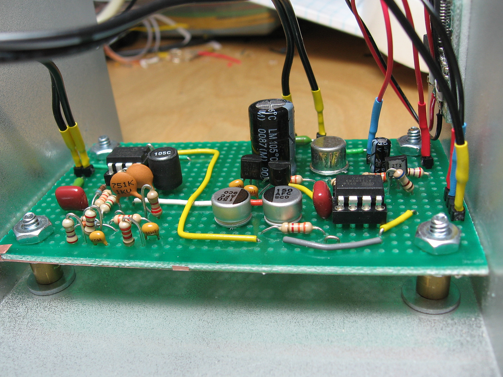
The end result was this cute little doodad:

Features:
- Isolated power supplies for the host computer, receiver circuitry, and the power line signal itself. Separate voltage regulators for analog and digital.
- High-Q LC filter, centered at 125 kHz.
- Dual outputs: RS-232 serial and USB (Prolific USB-serial chip)
- Generates human-readable text at 9600 baud:
HC=245 KW=001.347 V=121.228 CNT=033 - Decodes packets with up to 1 watt / 1 millivolt precision!
- Last but not least, an oh-so-cute power/status LED which glows dimly to indicate power, and flashes brightly when a packet is received.
With all of this precision, the resulting graphs look pretty decent. Here are power and voltage graphs, for the same time period. You can certainly see the voltage dips when my refrigerator or heater fan kick on, but you can also see some loads on the voltage graph that don’t show up on the power graph. These are probably the neighbor’s appliances.


The circuit design is pretty straightforward, and it should be pretty easy to build for anyone an AVR programmer and some experience with hobbyist electronics. Inside the box the mains voltage is split into two 9V AC transformers: one for power, and one for data. The power transformer’s output is rectified, and the unregulated voltage is diverted to two 7805 regulators, one for the microcontroller and one for the amplifier. The amplifier is very sensitive to noise, and it helps to have some isolation from all the high frequency harmonics that a microcontroller will toss into its power supply.
I built the prototype on a piece of stripboard in a grounded aluminum box. From left to right: MCP6292 dual op-amp and all associated passives, power supply, ATtiny85 microcontroller, and some transistors to drive the LED brightness control circuit and the RS-232 output.

The analog front-end starts with a high-pass filter which cuts out nearly all of the 60 Hz AC power, leaving a manageable signal level. This goes through some clamping diodes, to protect the op-amp input from transients, then through a first amplification stage with a gain of about 68. It’s important that this pre-amplifier is non-inverting, to avoid oscillation. This then goes through an LC bandpass filter, and another amplification stage with a gain of about 31.
With these op-amps, you could achieve higher gains (around 80), but this is all I needed. Your mileage may vary. If you want variable gain control, try replacing the 3.3k resistor at the second op-amp’s inverting input with a multi-turn 5k trimmer pot. More ambitious readers may even want to design an AGC circuit. After the second gain stage, a final low-pass filter is very important in order to remove transients that can cause false transitions on the microcontroller’s input. The microcontroller finally gets a filtered and amplified signal. It proceeds to do the demodulation and decoding in software.
I apologize for the crude hand-drawn schematic. There are more pictures on Flickr, and software/firmware in Subversion. Happy hacking!