
Tag: mini-project
-
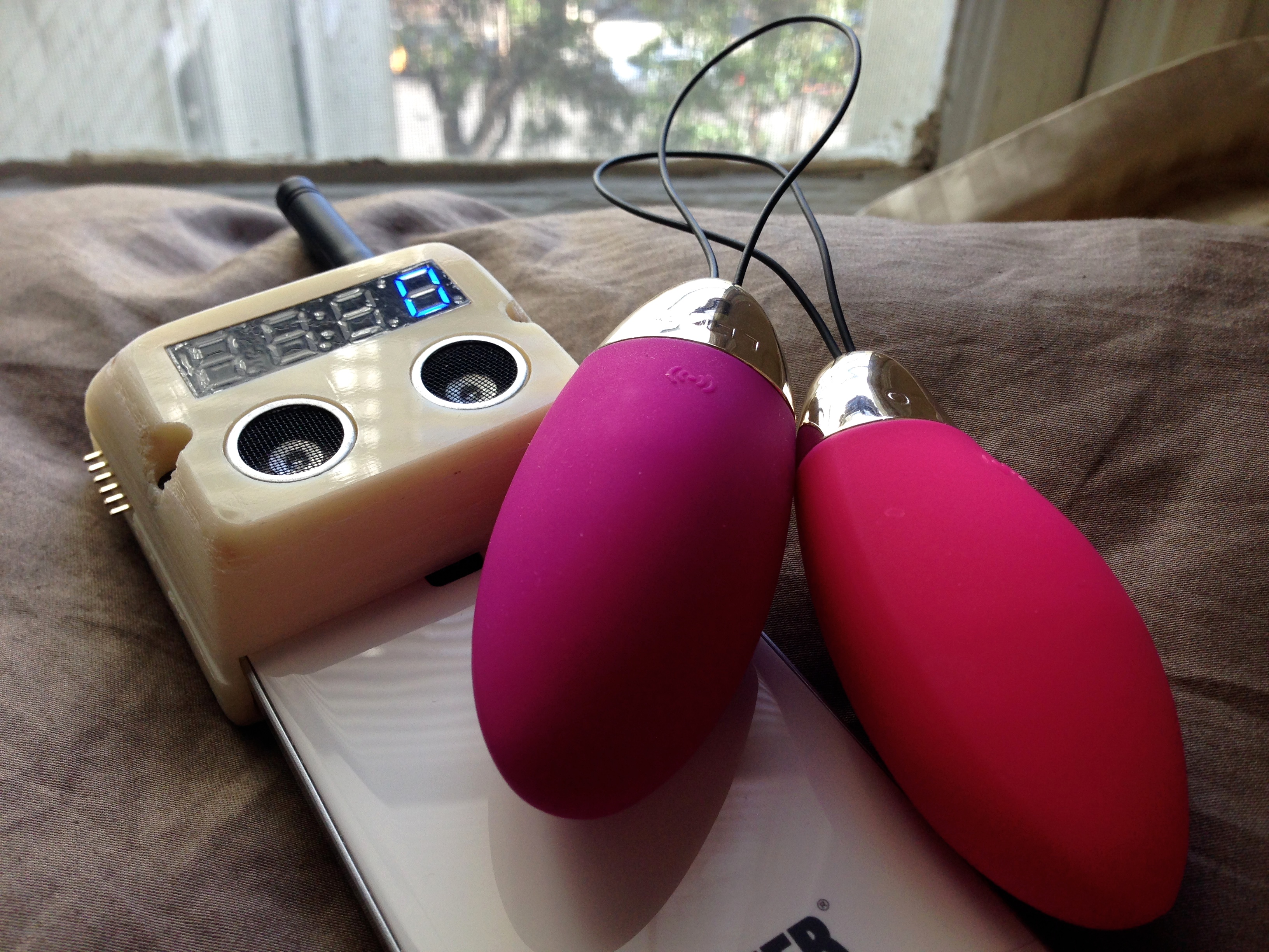
Hacking My Vagina
To me, a good sex toy helps form feedback loops. It doesn’t get in the way. A good toy gives you simple ways of exchanging signals with a partner or with your own body. It acts as a conduit. A good sex toy is analog.
-
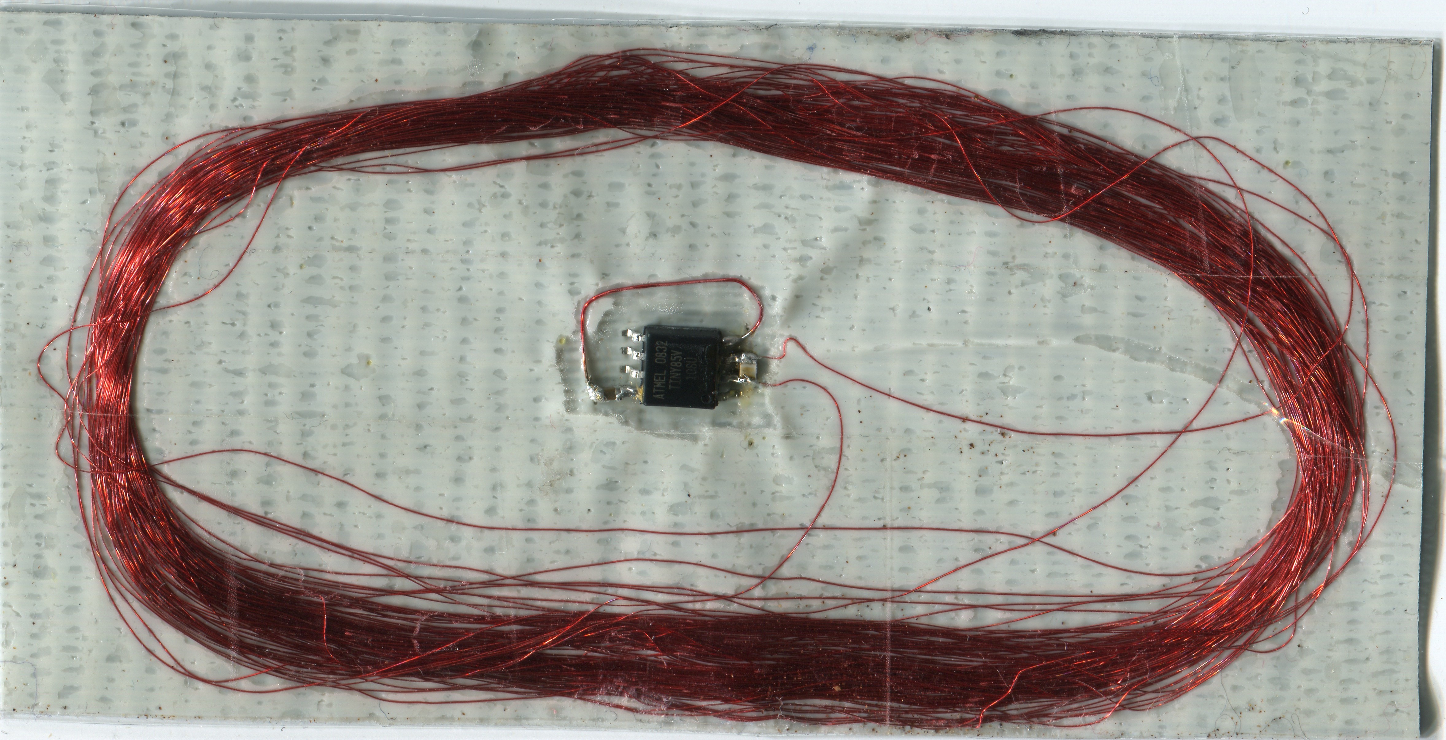
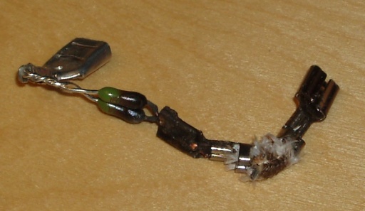
Duct tape RFID tag #1
This is just a messy first prototype, but I recently tried making an AVRFID tag on a substrate of duct tape. The first attempt involved: An upside-down strip of duct tape, as the base for everything else to stick atop 100 turns of AWG 40 magnet wire around a ~66mm diameter form, which I then…
-

Neon Scope
It’s so hard for me to clean up my office. I’ll see a random collection of objects that I’m supposed to be sorting, putting away, and/or throwing in the garbage.. and I can’t help playing with them instead. This time the objects in question were an old CCFL backlight inverter, a neon flicker-flame bulb, and…
-

Cube64 GameCube to N64 Adaptor
Enjoy retro N64 games, but can’t stand the controller? That’s the situation I found myself in about 7 years ago, back in 2004. So I built an adaptor, to use Game Cube controllers on the N64. (tl;dr… Cube64-DX on Google Code) The adaptor hardware is very simple- all you need is a PIC microcontroller. I…
-
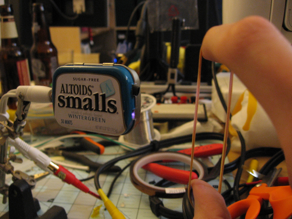
Simple Optical Microphone/Pickup
This is another mini-project that began, like so many have, in a discussion with Scott over some beer. We wanted to build a new kind of speaker amplifier, which used mechanical closed-loop feedback to position the speaker cone exactly where the audio signal says it should be. We figured that, if done right, this could…
-
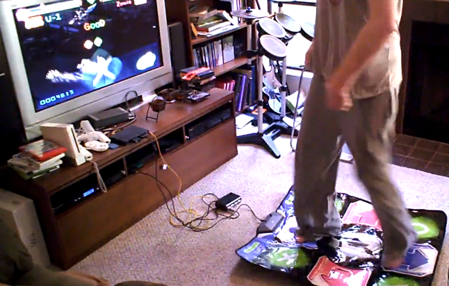
Gitaroo Man + DDR Pad
As much as I like the long, complicated projects that involve weeks of soldering, gluing, coding, tweaking, re-tweaking and debugging, it’s really refreshing to occasionally do something cool with no more than an hour or two of work. This mini-project was my boyfriend’s idea. It’s an experiment in cooperative two-player Gitaroo Man, played using a…
-
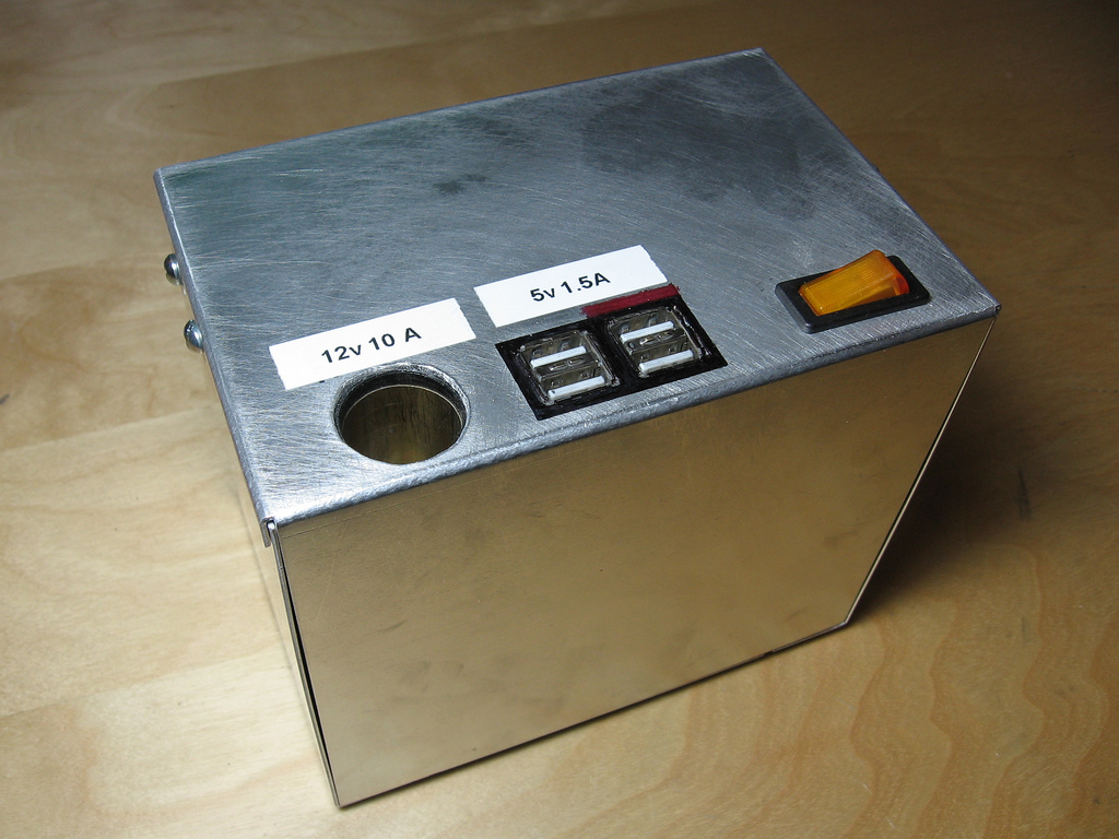
“Luggable” power pack
Paul and I are leaving on a cross-country train trip next week, for Jen and Shawn’s wedding in Colorado. I’m sure the view will be great, and I’m bringing a handful of books- but Paul and I are geeks and we need our electro-doodads. If only we had a way to run our Nintendo DS…
-
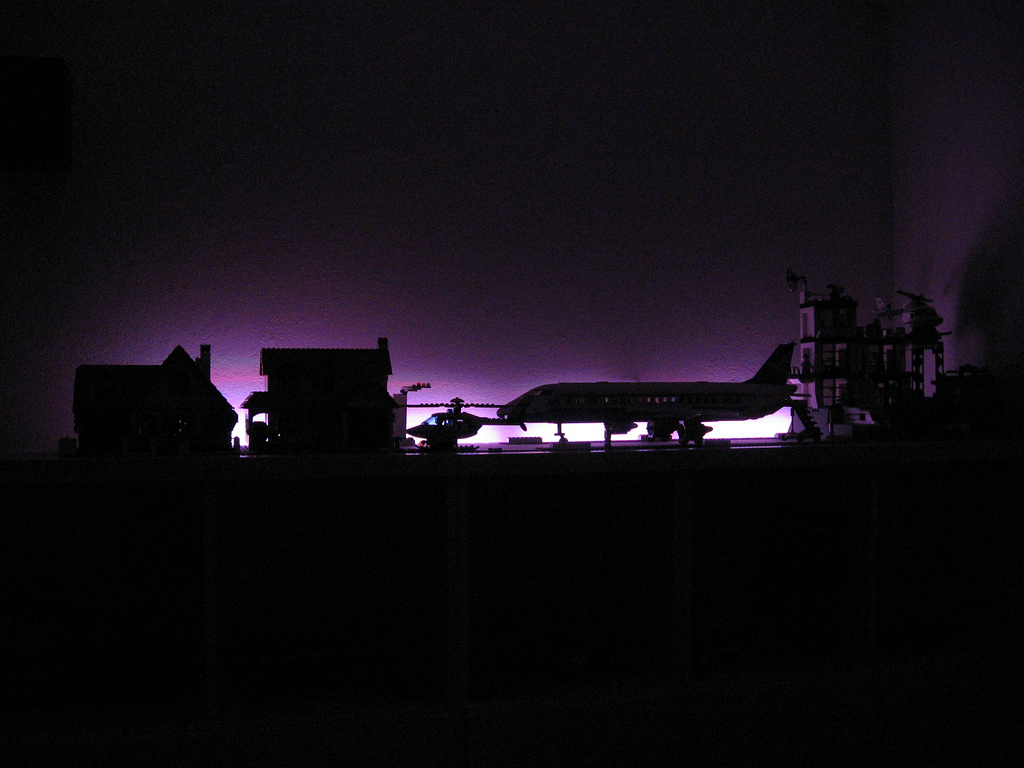
Lego Sky
Over the weekend, I had a chance to finish up a project that I started (and immediately became distracted from) several weeks ago. In our house, Paul and I have a game room. This is where the video games live, as well as other assorted geekery. We have Magic cards, D&D books, some manga.. it’s…
-
Mmm, crispy.
I hate power electronics. This was my first attempt at fixing a broken Cuisinart cordless kettle. The original symptoms: I notice the kettle occasionally turns itself off. If I turn it back on, it works again for a little while. This kept up for a day or so, then it refused to turn on at…
-
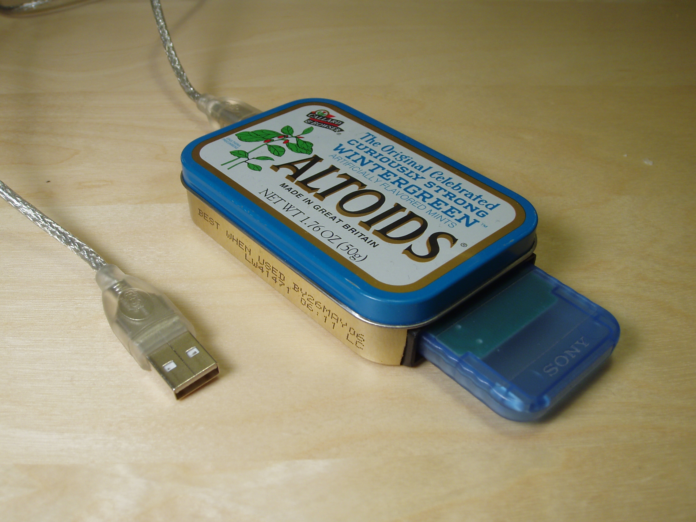
Latest Altoids artwork
Medium: Altoids tin, Keyspan USA-19HS (modified), PS2 Multitap (modified), 74HCT04 inverting buffer, discrete passive components, solder, wire, epoxy. Artist’s inspiration: Dorky boyfriend that crafts Final Fantasy Tactics characters with the precision of a meticulous dungeonmaster 🙂 (Yes, it’s a USB Playstation memory card reader/writer. Firmware and source code for Mac OS and Linux is in…
-

Flightaware route histogram
Flightaware + Fyre: The above image is part of a histogram generated from Flightaware’s 24-hour time lapse. Click the link for the uncropped version. The original video is a Quicktime wrapper around individual PNG frames. I used mencoder to strip off the Quicktime wrapper, then a small Python script split the video streams into individual…