Soft RFID tags and cuddly plushies

This week a new power tool arrived on my desk:

How did this happen? It was actually kind of complicated…

  1. Months ago, Scott and I dreamed of an automated kegerator. For the workplace, naturally. We’d need some way to hand out credits that coworkers could use in order to dispense beer, so we’d need a way to identify people or otherwise store these credits. We could use some kind of “credit card”, but that’s so last century. I wanted to just use the proximity ID badges we already had as employees.
  2. So, I got interested in RFID technology. It was also a decent excuse to brush up on analog electronics.
  3. I build an ultra-simple “software only” RFID reader that can read multiple card formats, including our ID badges.
  4. Hey, wait, I can read my prox card now… I can make an RFID garage door opener
  5. Uh, what now? Readers are easy, how about making an RFID tag from scratch?
  6. My RFID tag works fine, but it’s kind of ugly. What if I could just build a cloned badge directly into the sleeve of a hoodie? Now I could just wave my arm at the door to get into the office.
  7. This leads me to do some more research on the LilyPad “wearable e-textile” technology developed by Leah Buechley at my Alma Mater.
  8. I order some conductive thread, buy a sewing kit at Target, and try my hand at making some RFID antennas.
  9. Sewing accurate and tightly spaced spirals by hand using really finicky thread is not fun. I think about buying a sewing machine.
  10. I’m really tempted by the Singer Futura Computerized Embroidery Machine, but the $800 price tag scares me off.
  11. After only moderate fuss and only about an hour waiting in line, I get a basic mechanical sewing machine (a Singer Inspiration 4210) from my local Jo-Ann’s.

Whew. Ok, I have a sewing machine. So what do I do with it?

Cloth RFID tag prototypes

I did end up making a working cloth RFID tag. This is a 2×3 inch iron-on patch with an antenna coil made of conductive thread. I sewed the bulk of the antenna by machine (and it would have been thicker if my thread hadn’t broke) then I did the more intricate bits by hand. The antenna itself is actually conductive only on one side, since I had insulating thread in the bobbin. I ran the conductive thread back from the outside of the coil to the center of the tag by sewing on the opposite side, so as not to short-circuit the coil. The black blob is an ATtiny85 microcontroller in a SOIC-8 package.

In this tag, I attached the chip to the antenna using conductive epoxy. In my next prototype, I’ll probably use crimp beads as Leah Buechley suggests. The antenna should also really use more ‘turns’ of thread. This tag works with my Parallax RFID reader, but the range is only a few millimeters. On the right is a larger coil I was sewing for practice. This one would have been larger too, but I had problems with the thread breaking.

I plan to make more prototype RFID tags, both to practice my sewing and to try and increase the range.

So, what else can I do with this machine? I had some fun with it:

IMG_0432

The red dude on the bottom is of course an anime smiley, which may or may not be from the Kingdom of Loathing universe. The “ears” and “legs” were totally unintentional, but I think it turned out pretty cute. Next I made the orange above it. It came out kinda lumpy, but it was good practice. I later practiced my vivisection skills by giving it the test-claw that I built while figuring out how to make my next critter- the cute yellow crab in the middle.

You may remember the crab from an earlier post of mine. It’s kind of a chibi version of Ikea’s KORALL KRABBA. They’re so cute together!

IMG_0444

There are a few more pictures in my Sewing set on Flickr ^_^

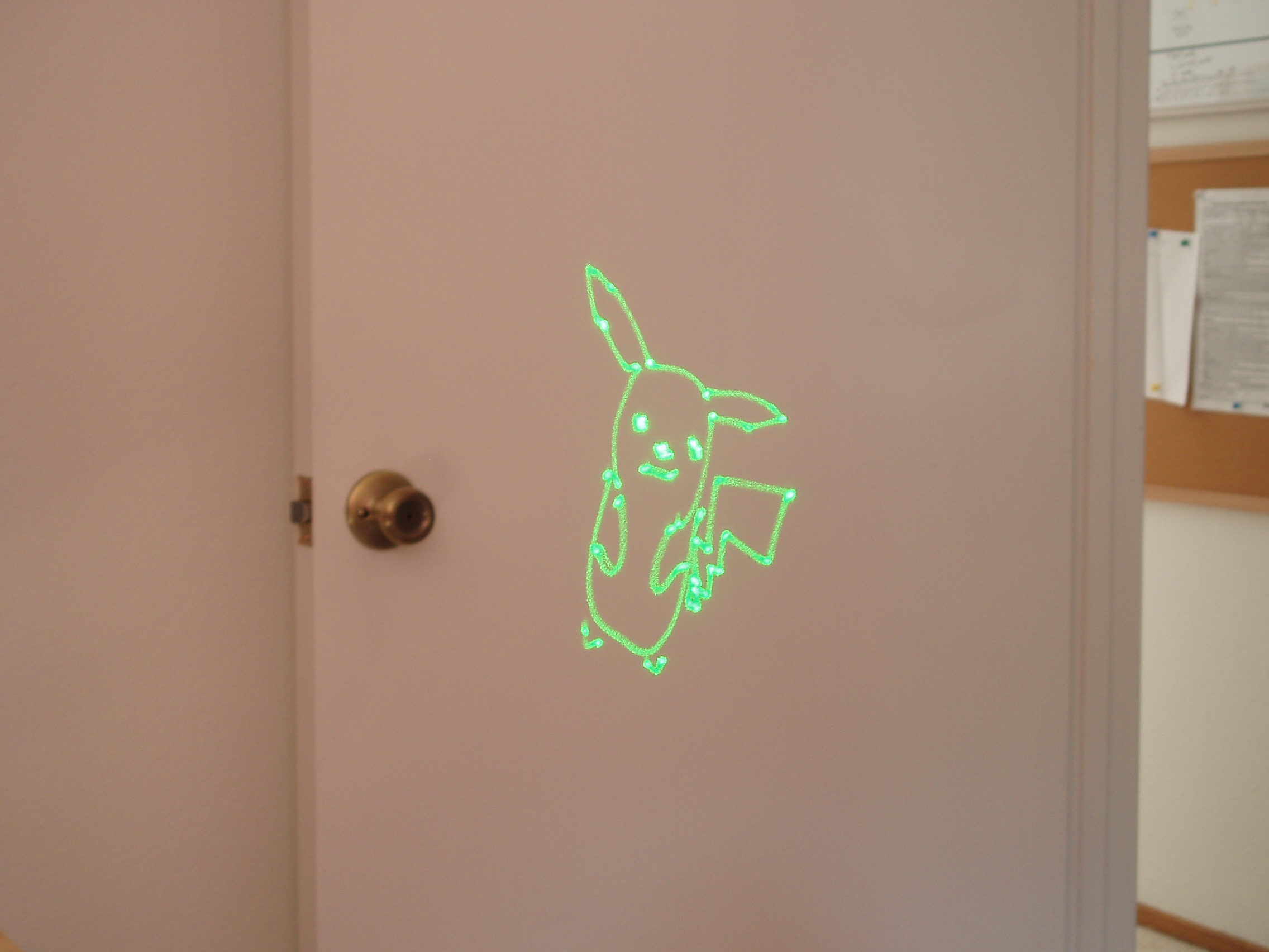
Laser projector update

Looks like my hard disk laser projector made the MAKE blog. Sweet 😉

I’ve been hacking on the software for the projector quite a bit this week- mostly on the code responsible for importing and converting vector graphics data.

In a typical laser projector, you have a high-speed DAC connecting a pair of analog servo amplifiers to a computer. The computer reads samples out of an ILDA file, maybe applies some effects in real-time, then sprays them out of the DAC. In my projector, I wanted a more sophisticated approach- mostly because of the relatively low-bandwidth Bluetooth link that exists between my projector and the PC.

My solution was to create a simple vector graphics virtual machine. The virtual machine runs on the projector’s microcontroller, in lockstep with the servo loops. It has three registers- a position register, a first-order accumulator, and a second-order accumulator. It isn’t turing-complete, but there are instructions to load these registers, wait for a number of samples to elapse, etc. It can interpolate quadratic Bézier curves in hardware. The VM also supports instructions like “jump”, and “increment counter”. This lets it support fairly complex queueing and double-buffering systems.

So far, I have code to:

  • Load paths from an SVG file
  • Convert those paths (lines, quadratic Bézier curves, and cubic Bézier curves) into my “VectorMachine” instructions.
  • Simulate the VectorMachine, and display a visual representation of the samples that the hardware will generate.
  • Queue up instructions for completed frames, using both a local and remote (in the firmware’s memory) queue. The queue has bounded latency, and it lets me flawlessly stream animated vector graphics over Bluetooth to the device.

There are some areas for improvement, like automatically optimizing the path the laser takes when it’s blanked. This could be fun- it’s actually a travelling salesman problem. I also don’t have a good way to get animation, or programatically generated graphics into it. But, it loads simple SVG files, and it does an okay job at it. It does a decent job at rendering Kirby at a blazing fast 8 FPS.

I think it’s time to take a break from this project while I figure out what to do with it next. Maybe music visualization, or Flash animations?