I’ve been spending more time hacking on Robot Odyssesy lately. Most of it has had a specific purpose… I’ll write a separate blog post on that project once it’s a bit more fully baked. In the mean time, the reverse engineering has had some useful side-effects.
Chip Simulation
If you haven’t heard of Robot Odyssey, it’s a game where you build logic circuits that control robots in order to solve puzzles. You can build circuits directly inside the robots, but you can also program them into ‘chips’- small 8-pin integrated circuits. The game also comes with several chips: a clock generator, 4-bit counter, and the infamous “wallhugger”, a chip you can stick in your robot to have it follow the walls of a maze.
Once you ‘burn’ a circuit into a chip, you can load and save it but you can’t see inside. So this has made the built-in chips a bit of a mystery. There’s no way in-game to see how they work, and for all we know they could be ‘magic’ in some way. I had speculated a bit on how they store the compiled chips. Was it some kind of super-optimized machine code? Or maybe some kind of encoded Programmable Array Logic that was especially quick to simulate on an 8086 processor?
Well, it turns out that the code for simulating chips is clever in places, but the file format is quite straightforward. It’s sort of halfway between an electrical netlist and a bytecode language. On every in-game clock tick, every bytecode instruction in the chip executes in order. Instructions can represent logic gates (AND, OR, XOR, NOT, RS flip-flop), or they can enter/exit a nested chip. Bytecode parameters can be one of two data types: The state of a pin, or a list of pin addresses.
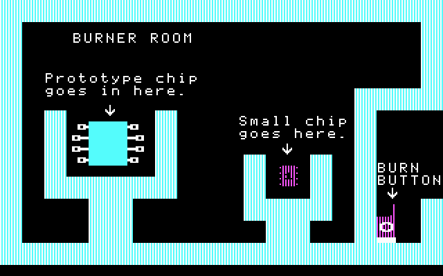
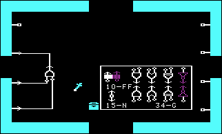
Here’s a really simple circuit inside the Robot Odyssey prototype chip:
And this is the top of the .CSV (Chip Save) file that the game produces:
00000000  00 00 00 00 00 00 00 00  01 00 00 00 01 ff 07 00  |................|
00000010  02 00 09 ff 00 03 00 0a  ff ff ff ff ff 00 00 00  |................|
- First 8 bytes: Pin states. All pins are off.
- First opcode (01). This is an AND gate.
- Pin states for the AND’s inputs. Both are off. (00 00)
- A list of 16-bit addresses that will receive this gate’s output.
- Address of Pin 2 (00 01)
- End of list (FF)
- Second opcode (07). This exits a chip. Since this is the outermost chip, after this opcode is the end of the chip’s electrical data. The parameters for this opcode are a list of lists which describes ‘nodes’, or places where we need to copy a pin state directly from one place to another.
- First list:
- Source address (00 02). This is Pin 3.
- First destination (00 09). This is the first pin of the AND gate.
- End of list (FF)
- Second list:
- Source address (00 03). This is Pin 4.
- First destination (00 0a). This is the second pin of the AND gate.
- End of list (FF)
- End of list (FF)
- First list:
- Afterwards is garbage. In this case, (FF FF FF). This is probably left over in memory at the time the chip was compiled, and doesn’t mean anything. The chip interpreter doesn’t read this data.
Chip Disassembler
So, I figured out (I think) the entire file format, and wrote a Python script to disassemble it into something a little more human-readable. The above example chip disassembles to:
Sample Chip Disassembly
Chip1 {
    HELP       'SPIFFY SAMPLE CHIP'
    HELP       '1'
    HELP       '2 OUTPUT'
    HELP       '3 INPUT 1'
    HELP       '4 INPUT 2'
    HELP       '5'
    HELP       '6'
    HELP       '7'
    HELP       '8'

    PIN        Chip1_pin2<0> 'out'
    PIN        Chip1_pin3<0> 'in'
    PIN        Chip1_pin4<0> 'in'

    AND        AND1_in0<0> AND1_in1<0> => [Chip1_pin2<0>]
    Node       Chip1_pin3<0> => [AND1_in0<0>]
    Node       Chip1_pin4<0> => [AND1_in1<0>]
}
Wallhugger Disassembly
For a more exciting example, now we can finally see inside the wallhugger chip! Converting this to a graphical schematic is left as an exercise to the reader 🙂
Chip1 {
    HELP       'Wall Hugger'
    HELP       '1 Top thruster    ^ Hook up pins'
    HELP       '2 Left bumper     ^ as described.'
    HELP       '3 Left thruster   ^ This chip will'
    HELP       '4 Bottom bumper   ^ cause a robot'
    HELP       '5 Bottom thruster ^ to follow(hug)'
    HELP       '6 Right bumper    ^ the walls of a'
    HELP       '7 Right thruster  ^ room.'
    HELP       '8 Top bumper      ^'

    PIN        Chip1_pin1<0> 'out'
    PIN        Chip1_pin2<0> 'in'
    PIN        Chip1_pin3<0> 'out'
    PIN        Chip1_pin4<0> 'in'
    PIN        Chip1_pin8<1> 'in'
    PIN        Chip1_pin7<1> 'out'
    PIN        Chip1_pin6<0> 'in'
    PIN        Chip1_pin5<0> 'out'

    OR         OR1_in0<0> OR1_in1<0> => [Chip1_pin5<0>]
    OR         OR2_in0<0> OR2_in1<0> => [OR1_in1<0>]
    OR         OR3_in0<0> OR3_in1<0> => [Chip1_pin3<0>]
    OR         OR4_in0<0> OR4_in1<0> => [OR3_in1<0>]
    AND        AND1_in0<0> AND1_in1<1> => [OR2_in1<0>, OR4_in1<0>]
    OR         OR5_in0<1> OR5_in1<0> => [Chip1_pin7<1>]
    OR         OR6_in0<0> OR6_in1<0> => [OR5_in1<0>]
    AND        AND2_in0<0> AND2_in1<0> => [OR2_in0<0>, OR6_in1<0>]
    AND        AND3_in0<0> AND3_in1<0> => [OR6_in0<0>, OR8_in0<0>]
    OR         OR7_in0<0> OR7_in1<0> => [Chip1_pin1<0>]
    OR         OR8_in0<0> OR8_in1<0> => [OR7_in1<0>]
    AND        AND4_in0<0> AND4_in1<0> => [OR4_in0<0>, OR8_in1<0>]
    NOT        NOT1_in0<1> => [AND1_in0<0>, AND3_in0<0>, AND4_in1<0>, AND2_in0<0>]
    OR         OR9_in0<1> OR9_in1<0> => [NOT1_in0<1>]
    OR         OR10_in0<0> OR10_in1<0> => [OR9_in1<0>]
    OR         OR11_in0<0> OR11_in1<1> => [OR9_in0<1>]
    Chip2 {
        PIN        Chip2_pin1<1>
        PIN        Chip2_pin2<0>
        PIN        Chip2_pin3<0>
        PIN        Chip2_pin4<0>
        PIN        Chip2_pin8<1>
        PIN        Chip2_pin7<0>
        PIN        Chip2_pin6<0>
        PIN        Chip2_pin5<0>

        FF<01>     FF1_in0<0> FF1_in1<1> => [Chip2_pin5<0>] []
        OR         OR12_in0<0> OR12_in1<0> => [FF1_in0<0>]
        OR         OR13_in0<1> OR13_in1<0> => [FF1_in1<1>]
        OR         OR14_in0<0> OR14_in1<0> => [OR13_in1<0>]
        OR         OR15_in0<0> OR15_in1<0> => [OR12_in0<0>]
        OR         OR16_in0<0> OR16_in1<0> => [OR15_in1<0>]
        FF<01>     FF2_in0<0> FF2_in1<1> => [Chip2_pin6<0>] []
        OR         OR17_in0<0> OR17_in1<0> => [FF2_in0<0>]
        OR         OR18_in0<0> OR18_in1<1> => [FF2_in1<1>]
        OR         OR19_in0<0> OR19_in1<0> => [OR17_in0<0>]
        OR         OR20_in0<0> OR20_in1<0> => [OR19_in1<0>]
        OR         OR21_in0<0> OR21_in1<0> => [OR18_in0<0>]
        FF<01>     FF3_in0<0> FF3_in1<1> => [Chip2_pin7<0>] []
        OR         OR22_in0<0> OR22_in1<0> => [FF3_in0<0>]
        OR         OR23_in0<0> OR23_in1<1> => [FF3_in1<1>]
        OR         OR24_in0<0> OR24_in1<0> => [OR22_in0<0>]
        OR         OR25_in0<0> OR25_in1<0> => [OR24_in1<0>]
        OR         OR26_in0<0> OR26_in1<0> => [OR23_in0<0>]
        FF<10>     FF4_in0<1> FF4_in1<0> => [Chip2_pin8<1>] []
        OR         OR27_in0<1> OR27_in1<0> => [FF4_in0<1>]
        OR         OR28_in0<0> OR28_in1<0> => [FF4_in1<0>]
        OR         OR29_in0<0> OR29_in1<1> => [OR27_in0<1>]
        OR         OR30_in0<1> OR30_in1<0> => [OR29_in1<1>]
        OR         OR31_in0<0> OR31_in1<0> => [OR28_in0<0>]
        Node       Chip2_pin1<1> => [OR30_in0<1>, OR13_in0<1>, OR18_in1<1>, OR23_in1<1>]
        Node       Chip2_pin2<0> => [OR25_in0<0>, OR31_in1<0>, OR21_in0<0>, OR14_in1<0>]
        Node       Chip2_pin3<0> => [OR20_in0<0>, OR28_in1<0>, OR26_in0<0>, OR14_in0<0>]
        Node       Chip2_pin4<0> => [OR16_in0<0>, OR31_in0<0>, OR21_in1<0>, OR26_in1<0>]
    }
    Node       Chip1_pin2<0> => [OR7_in0<0>, OR10_in0<0>, Chip2_pin2<0>]
    Node       Chip1_pin4<0> => [OR3_in0<0>, OR10_in1<0>, Chip2_pin3<0>]
    Node       Chip1_pin8<1> => [OR5_in0<1>, OR11_in1<1>, Chip2_pin1<1>]
    Node       Chip1_pin6<0> => [OR1_in0<0>, OR11_in0<0>, Chip2_pin4<0>]
    Node       Chip2_pin8<1> => [AND1_in1<1>]
    Node       Chip2_pin7<0> => [AND2_in1<0>]
    Node       Chip2_pin6<0> => [AND3_in1<0>]
    Node       Chip2_pin5<0> => [AND4_in0<0>]
}
Download it
If you want to try it out yourself, or you want more detailed info about the file format, grab the latest source code here: