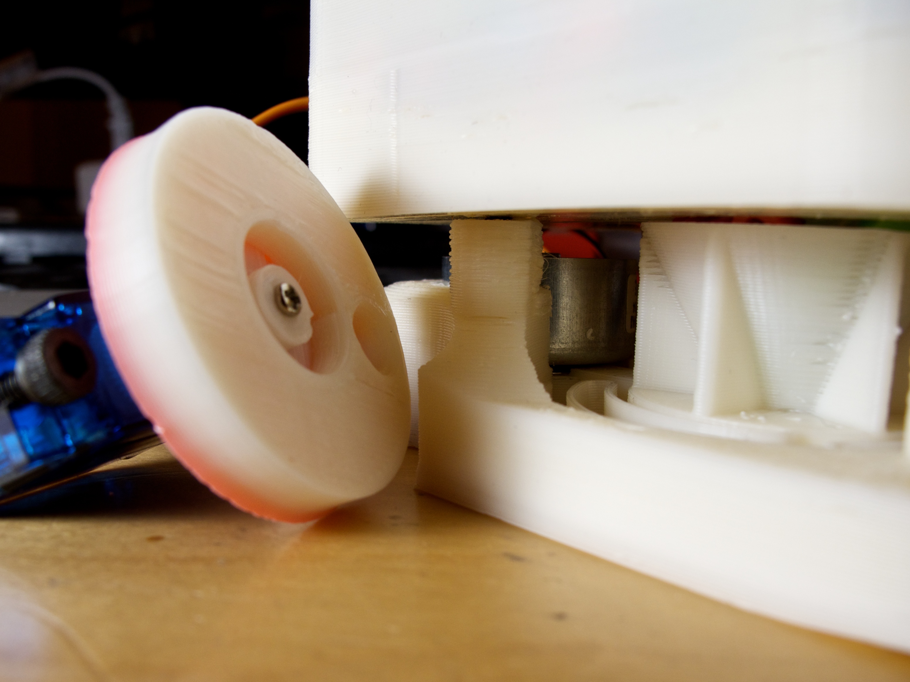
scanlime050 – Perler Bead Shaker

Briefly looking back at an old project where I tried to push the capabilities of the first 3D printer I had, the Makerbot Thing-o-Matic designed in late 2010. This project from 2011 was intended to be a full printer or sort and place machine for fusible “Perler” style plastic art beads. I got as far as designing a vibrating funnel, hopper, and part of a color sorting mechanism.

The old Perler Bead Robot project is still on Thingiverse.

And perhaps more useful is the library for making 2D springs in the same style.

Thank you so much for watching, subscribing, and sharing my videos. And a special thanks to my supporters on Patreon, where recurring donations make this content possible.

For an alternative to youtube and twitch, check out Diode Zone.

If you’d like some of those cool scanlime stickers or Servo AF stream gear, check out the shop.

For previous episodes, check out the full scanlime playlist.

Each episode is compiled together from many livestreams which you can hang out with on the companion scanlime-in-progress channel.

Follow @scanlimelive for live streaming announcements.

Perler Bead Robot Ideas

More parts for the Perler Bead robot

This was originally going to be a comment response to Tim’s blog entry, Scanlime’s Perler Bead Hopper Sorting Suggestion:

I was looking at Scanlime’s 3D Printed Vibrating Perler Bead Hopper: and I was thinking how best to sort out the different color beads. I thought that if scanlime used one main hopper with the color sensor ([photo] & [sparkfun]) and one hopper for each color. There would need to be a way to put the bead in the correct hopper for each color. I was thinking that a rail and belt system like the X (maybe Y I don’t know) of a Reprap Mendel to move the main hopper/color sensor to the correct hopper. There would also need to be a tilting platform to drop the bead into the correct hopper for that color. I decided to make a 3d layout of my ideas.

But then it started to get longer, then I wanted to include diagrams… so here we are 🙂

Good idea, Tim, and thanks for the writeup. I had thought about various ways of sorting the beads out per-color. This method looks like it’d be good at storing larger bulks of colored beads. Originally, I’d been thinking about using a rotating magazine of cylinders that held vertically stacked beads. Here’s a crude pencil sketch of that idea. There would be some sort of gate mechanism to let one bead through at a time. One possibility is a rotating drum like the one I printed above. The other, shown in the sketch, is a scheme involving two alternating levers or hammers. One holds bead N, one holds bead N-1.

I might try one of these sorting approaches for a second revision of the robot. But for the first revision, I wanted to keep things simple. A minimum of moving parts, a minimum of things to go wrong. For example, what happens if you have a color in your hopper that never gets used in the design? Eventually that sorting bucket will overflow, and you need a way to handle that. Is there some other discard area that you use when the sorting bucket overflows? This all adds more complexity to the design.

I saw a different way to approach the problem. Instead of moving to a particular location on the build surface, then looking for a bead of the right color, I wanted to do the opposite. Get a bead, any bead. Figure out what color it is. Then do something with it. Looking at the problem this way, instead of searching for a particular bead, you’re searching for a place to store it. Maybe I’m just too big a computer nerd, but it starts to look like a storage or memory system to me.

The simplest solution would involve only three moving parts:

  • A build surface, with some sort of X/Y motion
  • The hopper with vibrating funnel
  • A gate, drum, disk, or any other way of releasing a single bead at a time

With these parts, your build procedure looks like this:

  1. Turn on the vibration motor
  2. Wait until the color sensor detects a bead (Reflected light is above a set threshold)
  3. Turn off the vibration motor
  4. Based on the sensed color, find a location for the bead and move there. Preferably the closest location on the grid where that color bead is used. If we don’t need any more beads of that color, we can dump the bead on the floor.
  5. Use the gating mechanism to release a single bead.

My current plan is basically this, but with one small optimization. My gating mechanism is a 3D-printed disc that has a tapered shape which (I hope) will capture a single bead without jamming, even if the bead heights vary a little bit. The disc starts out in a centered position, directly below the vibrating hopper and directly above the color sensor. When we want to let a bead through, the disc rotates. The solid portion of the disc blocks the exit from the vibrating funnel, while the bead is deposited in a chute that leads to the build platform.

Since the disc is driven by a hobby servo, I can easily add two exit chutes. If I rotate clockwise, for example, I could deposit the bead on my build surface. If I rotate counter-clockwise, it could go directly to a discard/recycle chute without taking the time to move the build platform at all. I have some more chicken-scratch to illustrate this design:

I suspect it will work alright, especially since the current plans I’m hatching for build surface movement might actually be really fast. (A perler bead robot needs much less accuracy than a RepRap or Makerbot!)

However, if it needs to be faster, a sorting system like your reprap-style trolley or my rotating magazine would function like a cache. It lets you break the problem into two stages, first storing the beads in buckets/cylinders, then placing them. Since you get an extra degree of freedom, now we can start to make some optimization choices in software. Perhaps a better analogy even is instruction reordering in a CPU. Using the sorting bins, we can effectively “look ahead” some fixed (but perhaps very large) number of beads, and optimize the path we use to place them.

I find it helpful to look at the extremes. If we had infinitely large sorting buckets, it would be trivial. We could sort all of the beads ahead of time if we really wanted to. Or we could run the sorting and placing tasks concurrently, with the placing task waiting on more beads when it runs out of a particular color.

If we had a zero-size sorting bucket, of course it looks like the sketch above. But if the sorting system was much smaller.. let’s say it only had room for a dozen beads. Then what would it be like? If we know what beads are coming, perhaps we can optimize the path we take. If the vibrating funnel gave us a blue bead, then a yellow bead, then a black bead, we could notice that there’s a blue bead and a black bead adjacent to each other in the pattern, and the machine could choose to place the beads out-of-order. A tiny sorting system like this could save almost as much time as a larger sorting system, and it could be much smaller and perhaps simpler.

So, in short, I agree it’s not the most efficient design, but I have a hunch that it’s a good tradeoff between complexity and operational speed 🙂

Update: I posted the work-in-progress design files on Thingiverse, as Thing 7332.

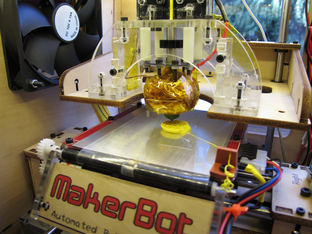
Getting to know the Thing-O-Matic

This post is mostly an apology for not having done anything blog-worthy in the past few months. As usual, life has been full of Things. Like Katamari Damacy. Kinda.

On the technical side, I’ve had a few interesting ideas bouncing around in my head lately:

  • 3D Printing. Seems like a space ripe for DIY innovation, and besides, it’s really cool.
  • Other sorts of odd CNC machines. Like a computer controlled sort-and-place for fabricating Perler Bead designs automatically.
  • Electronic Jewlery, assembled at microscope-scale. Ropes of twisted 40 AWG wire with LEDs soldered along them in a Charlieplexed matrix. That sort of thing. And perhaps I can make something half as pretty as Zelle‘s stuff.
  • You know, something actually important. Like solving world hunger, or making computers more efficient or more secure, or solving Big Problems in human rights. But who has time for that, let’s play with microcontrollers.

Starting at step #1 then, I recently got the Makerbot Thing-O-Matic kit that I preordered. It’s pretty cool- a relatively cheap way to get into 3D printing, and every single part is open source and hackable.

Makerbot with thing-collection system

Starting a build (closeup)

Companion Cube

This is my first 3D printer, so I’m not really qualified to write a review of it just yet. But I can briefly list the things I like and don’t like about the kit.

Things that rock:

  • It’s relatively easy to put together. I got my kit on a Friday afternoon and had time to get it printing by (late) Sunday night while also taking a day off to socialize.
  • With default settings and pretty much no futzing with the belts or Skeinforge, the print quality is pretty fair. And with only a bit of tweaking, you can do decent prints at a 0.4mm layer height.
  • From what I can see, the mechanical parts are fairly good. Feed rates seem relatively fast for a low-cost CNC machine, and while the machine as a whole tends to wobble and vibrate a lot, the machine is quite rigid where it counts.
  • The MK5 extruder has a very solid mechanical design, and it grips the plastic filament quite heartily.
  • The conveyor belt is cool, and it was fun printing several parts back-to-back without manual intervention.

Things that annoy me:

  • The motor on the MK5 extruder. This motor bugs me. A lot.
    • For starters, mine had a common problem in which the motor stalls randomly, overheats the H-bridge, and generally makes a mess of the whole system. I traced this back to a particular mechanical state in which the motor needs upwards of 2 Amps to un-stall, when it normally runs at less than 50 mA. Ow. This is more current than the H-bridge can handle, so it just gets hot and the motor goes nowhere. Right now I’m working around the bug by using a relay to drive the motor, but that’s a dreadful hack.
    • Even when the motor works, the extrusion rate is unpredictable and uncontrollable. The extruder controller’s PWM is worse than useless (The docs warn of it damaging the motor?) and even at a constant voltage, the actual extrusion rate changes based on lots of factors- age of the motor, tension on the filament drive gear, phase of moon. So the thickness of the extruded plastic is, in turn, quite variable.
  • The conveyor belt easily warps and twists. It’s really convenient, but for larger or high-res prints it just isn’t rigid enough. I think I could fix this by building a tensioner for the belt, but for the moment I’ve just taken my belt off. Right now I’d rather print one thing accurately than print 100 copies of something inaccurately 🙂
  • The electronics and firmware seem a bit.. I hesitate to say this, but, amateurish? I can’t help but think that there’s a better processor for the job than an AVR, and I think the Arduino layers are getting in the way more than they’re helping. The modular design also seems like needless complexity. Six PCBs? Really?
  • The software which generates toolpaths, Skeinforge, is actually quite nice and configurable. Now I’m just about the biggest Python fan of anyone I know in person, but I still get very frustrated by how slow this tool is on more complex models. It also seems to frequently do rather bizarre things- like generating toolpaths that could easily be one continuous segment, but are instead several disjoint plastic threads that are placed down in very suboptimal order.

So, naturally I have some plans to rectify these annoyances:

  • I’ve already ordered a Makergear stepper extruder with 0.35mm and 0.25mm nozzles. Can’t wait to try this out!
  • I’m tempted to try my own toolpath generator. I know everyone and their mom are writing Skeinforge replacements these days, but it seems like this could be a fun project to tie in with my interest in computer graphics and graphics-related algorithms.
  • I’m also quite tempted to design my own all-in-one controller board for Makerbots and RepRaps. I’m picky about these sorts of things, so I really want some real-time guarantees in the motor controllers, and I want to never have to worry about the processor reading in g-code slower than the motors can move. So I’ve been thinking about doing something based on an XMOS, Propeller, FPGA, or ARM. And it’d be one PCB, with one processor, and all of the stepper drivers and FETs onboard. Anything else would just be a waste of board space and wire. I also kind of want a faster uplink to the PC, either Ethernet or USB 2.0.

So, we’ll see if these go anywhere… All of the above ideas are just ideas now, and their implementation or lack thereof is subject to my level of boredom!