
This is another mini-project that began, like so many have, in a discussion with Scott over some beer. We wanted to build a new kind of speaker amplifier, which used mechanical closed-loop feedback to position the speaker cone exactly where the audio signal says it should be. We figured that, if done right, this could yield higher audio quality from cheaper speakers.
So, that idea is pretty crazy, but it seemed just barely plausible enough that I had been thinking about the component parts of such an amplifier. The most important seemed to be a sensor that could accurately supply feedback on the speaker cone position without loading the speaker or distorting the cone. The first method we considered was a capacitive pickup. Paint the back of the speaker cone with conductive paint, then position two copper plates behind the cone, just barely not touching when the speaker is at its maximum throw. This acts like two capacitors in series, and gives you a capacitance that varies along with the audio frequency, without any mechanical connection to the speaker cone.
We also considered magnetic feedback, using something like an LVDT, but where one coil is the voice coil itself. This would involve modulating some kind of high-frequency carrier into the speaker drive signal, then placing another fixed coil around or behind the voice coil to pick up that signal.
The next method, and I guess the simplest, is optical. This would work a lot like a fiber optic microphone or an optical guitar pickup. You can measure vibration by detecting changes in light intensity caused by changes in distance or angle of some reflective thing that’s vibrating.
Whereas the capacitive and LVDT ideas require a high-frequency modulated signal, that’s optional with the optical method. You can measure absolute intensity, or you can modulate your LED with a high-frequency carrier that can be detected on the receiving end. This modulation can help reject ambient light (including hum from fluorescent lights) but it isn’t required.
So, to see if this project has even a tiny chance of working, I thought I’d prototype the optical sensor by building an optical microphone. The end results were rather mediocre. I’m posting it here only because:
- I was honestly surprised that it worked at all
- It could be useful for other applications, like a drum or bass guitar pickup
- Maybe one of my readers has hints on making it more sensitive and lower noise? 🙂
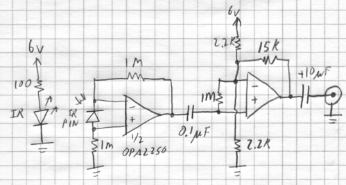
The Circuit
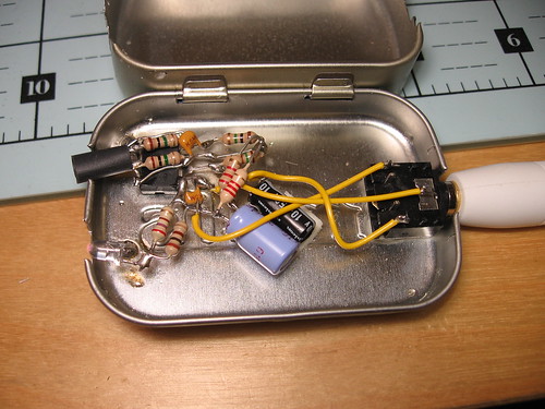
This is a really simple back-of-the-envelope sort of transimpedance amplifier, high-pass filter, and gain stage. Disclaimer: I hate doing math for analog circuits when it’s just a quick hobby project, so I did no math in designing this. Take it with a few shakes of salt. My breadboard was humming pretty badly due to incoming EMI, so I built it dead-bug style in a mini Altoids tin. If you build this, definitely use a suitable amount of shielding.
- Power supply range is about 3-6v, but it seems to work best at 5-6v. (If you listen to the op-amp data sheet, max voltage is 5.5v.)
- The op-amp should be a low-offset, rail-to-rail, high-bandwidth type. I used the OPA2350 because that’s what I had handy.
- The IR LED I used is pretty generic. I’m operating it at fairly high current, because I wanted a strong light source. You might consider using multiple LEDs, though, to make it easier to position the pickup properly.
- The photodiode should be a PIN diode with an IR filter. I used an SFH229.
- Keep the leads short, especially power and photodiode.
- They aren’t on the schematic, but remember some decoupling capacitors. (I used 0.1uF and 22uF)
- I put a bit of black heat shrink tubing around the photodiode as a baffle. This seemed to help.
- I used a stereo 1/8″ audio jack for ground, audio out, and power in. It would be neat to build one with a built-in battery, but this tin was a bit small for that, and the IR LED is kind of power hungry.
- Make sure to ground the Altoids tin! These smaller tins are harder to solder to than the larger tins, but it can be done. Just use a hot setting if your iron has adjustable temperature, and be patient.
Rubber Band Pickup
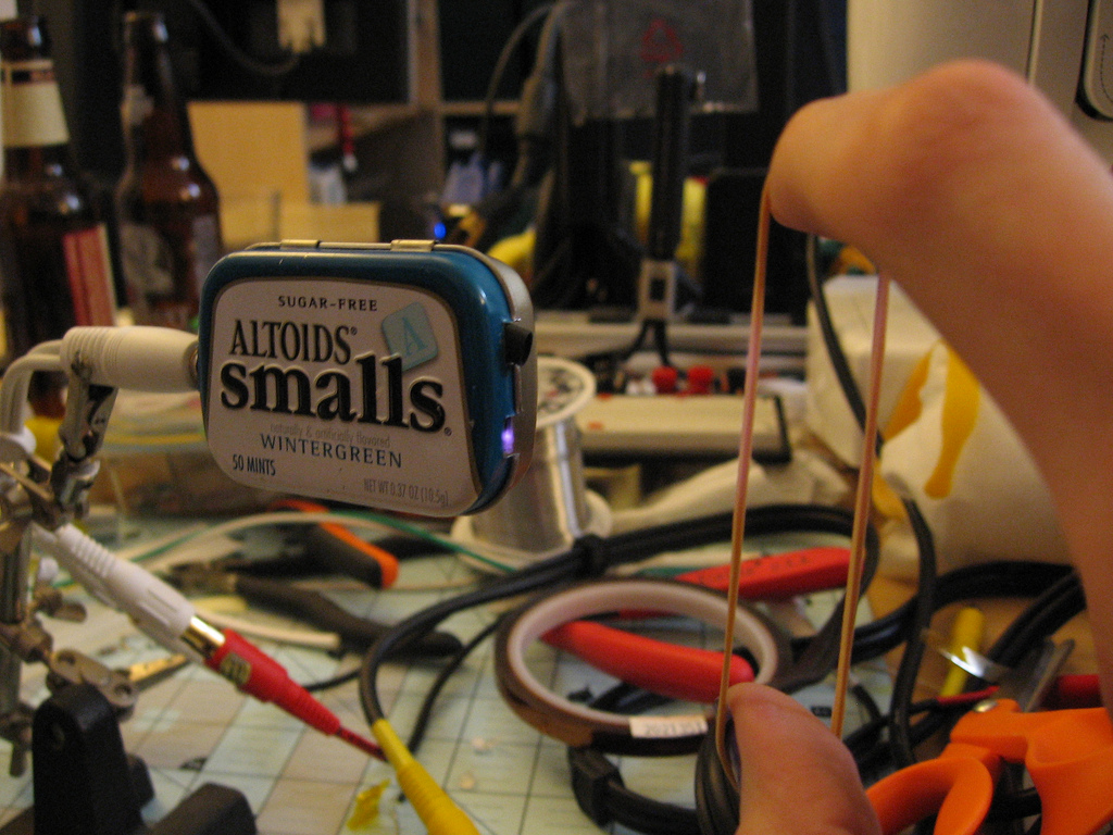
The first successful test I had of this pickup was with a rubber band. I’d like to try this with a guitar string, but I don’t play 🙂
It’s actually pretty forgiving about the positioning of the pickup relative to the rubber band, and it’s very sensitive even when the rubber band is a few inches away. This circuit can pick up very low-frequency vibrations well, so you hear very deep bass notes that you don’t normally notice in a rubber band pluck.

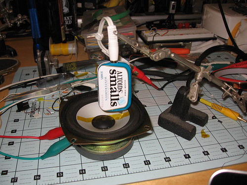
Speaker Surface Pickup
This is the application I originally hoped the optical microphone would work for: picking up sound off the front or back surface of a loudspeaker cone. If I could do this really well, the closed-loop amplifier might have a chance. The results certainly weren’t hi-fi, but I guess I was still surprised it worked at all.
Unlike the rubber band, this test was extremely finicky. I had to position the pickup just right, and I used some Kapton tape to make the surface of the speaker more reflective to IR light. I also had trouble getting a good reflection off the curved surface of the cone, so I stretched a flat section of tape between the center dome and the middle of the cone. This gave good signal strength, but the tape itself also acted as a mechanical filter, giving kind of an odd frequency response to the whole system.
And that is all.
Hopefully this will allow me to have some closure on a completely mediocre mini-project that was nonetheless interesting enough that I couldn’t just forget about it without sharing. 🙂 If anyone reading is a real electrical engineer, I’d be interested in hearing about what I did wrong.